Removal and Replacement Procedures
6–72
AM700 Audio Measurement Set Service Manual
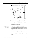
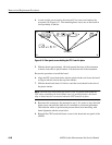
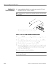
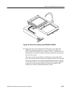
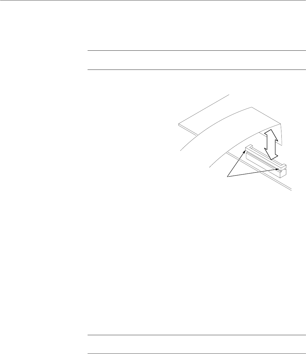
1. Release the disk drive flexible circuit board connector on the CPU board.
See Figure 6–36 for the connector operation.
NOTE. Do not pull on the cable to force it out of the connector. This will weaken
the connection.
Lift the connector release bar from its ends to loosen the cable.
Press the release bar down to lock the cable to the connector.
Figure 6–36: Disk drive flexible circuit board connector operation
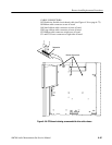
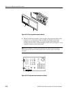
2. Remove the T15 Torx screws holding the disk drive mounting bracket to the
chassis.
3. Slide the disk drive and mounting bracket toward the rear of the AM700 to
clear the front of the disk drive from the front panel casting.
4. When the disk drive is clear separate it from the AM700.
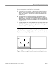
5. Separate the disk drive from the mounting bracket by removing the crosstip
screws that hold the disk drive to the mounting bracket using a P1 crosstip
screwdriver. The disk drive unit may have either two or four mounting
screws, depending on the vendor.
Reverse the procedure to reinstall the disk drive.
NOTE. The disk drive housing must be well centered in the front casting to allow
the trim ring to fit properly.
Disk Drive (A12)
Removal/Replacement


