


Theory of Operation
AM700 Audio Measurement Set Service Manual
3–39
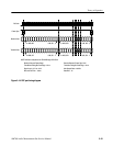
Communication between the CPU and DSP is done through the host port, J17. A
bidirectional buffer, U86, isolates the CPU and DSP busses from each other and
controls the direction of data transfer.
The Serial Control Register receives control bits in a serial data stream from the
Serial Control PAL. The register is composed of six, 8-bit serial input shift
registers, for a total of 48 control signal outputs. These bits are used to control
the switching for the Tunable Bandpass Filter, the A Channel and B Channel
Gain/Attenuator selections, the generator output impedance choices, and also to
provide control signals to other devices on the Analog Generator circuit board.
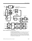
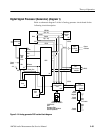
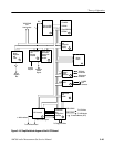
DACs and Current to Voltage Converters (diagram 3)
Refer to schematic diagram 3 of the A5 analog generator circuit board for the
following circuit description.
The clocks and serial data from the Generator DSP are buffered by U24 to
provide drive the the Clock and Data Isolators, U20 and U21. These isolators
maintain the floating capability of the Analog Generator.
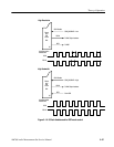
In High Resolution mode, this oversampling filter has interleaved left/right
16-bit serial data at 48 kilosamples/second applied. The filter deinterleaves the
data into left and right 20-bit serial data outputs at 384 kilosamples/second. The
data bits are clocked into the left and right DACs simultaneously by the bit clock
signal, BCKO, at 12.288 MHz. When the complete frame has been received, the
word clock signal, WCKO, tells the DACs to latch the word data and convert.
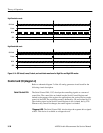
In High Bandwidth mode, the interleaved serial data is received at 192 kilosam-
ples/second. There are two paths for the data, a left data path through a 24-bit
data shifter, and an undelayed right data path through U96B. The data shifter is
formed by three, 8-bit serial-in, parallel-out, registers. The eighth bit of each is
the only output used so the left channel data is delayed by 24 bit clocks from the
right channel data to deinterleave the left and right data to the DACs.
The Data Selectors, U39 on the left channel and U38 on the right channel, are
driven to select data and clocks for the High Resolution mode or the High
Bandwidth mode of generator operation.
Left and Right DACs are serially loaded with a 20-bit word by the bit clock
signal. At the word clock, the data is converted to a current output that represents
the value of the data word.
Host Port
Serial Control Register
Data and Clock Isolators
Oversampling Filter
Data Shifter
Data Selectors
DACs