


Theory of Operation
3–80
AM700 Audio Measurement Set Service Manual
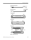
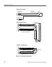
LCD Driver Board (A13)
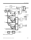
The LCD Driver board (block diagram shown in Figure 3–21) digitizes the
analog RGB output signals from the video display circuit into the correct digital
drive signals for the LCD display. The pixel format of the display is standard
VGA: 640 (H) × 480 (V). Signals output to the display are the following: 4-bits
each of R,G,B (red, green, and blue), vertical sync, horizontal sync, sampling
clock, enable signal, and two +5 V supply voltages. The horizontal display start
is delayed to meet the required timing for the LCD display. Both the horizontal
and vertical sync signals are negative sync.
Each analog signal (R, G, and B) is processed identically. The three signals are
applied to separate analog-to-digital converters (U9 Red, U10 Green, and U11
Blue). An operational amplifier associated with each ADC provides for color
gain and offset control. The analog signal is sampled by the ADC at the 25 MHz
delayed clock rate. The four bits just below the MSB (most-significant bit) of the
8-bit ADC are used for the digital data to the LCD, effectively providing a gain
of two for the color signals.
The digital data bits are clocked through two 8-bit latches, with the green and
blue data using all 8-bits of latch U13. The four bits of the red data are clocked
through latch U12. The remaining four bits of latch U12 and PAL U1 are used to
process the horizontal and vertical sync signals to provide delayed sync signals.
These signals are synchronized with the digital color information. Data is
clocked through the latches by a delayed 25 MHz clock signal.
The brightness control signal from the CPU board (derived from the setting of
the front-panel brightness control) is applied to the backlight inverter power
control circuit. A two-stage amplifier circuit (U4A and U4B) sets the intensity of
the LCD display by controlling the backlight inverter output voltage to the
backlight lamps. The second stage of the amplifier also provides a gain
adjustment (BRT R24) to set the level that turns off the backlight (no display). A
diode network on the output of the second stage shapes the slope of the BRT
control to be more exponential. The +13 VLCD power source is obtained from
the +15 V supply through two diode drops and some additional LC filtering.
Color A/D Converters
Digital Color Data Latches
LCD Brightness Control