


Diagnostics
6–30
AM700 Audio Measurement Set Service Manual
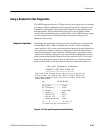
Viewing Diagnostics on a Remote Terminal
To view the diagnostics results on an external terminal, section 3 of switch S2 on
the CPU board, must be in the open position. This routes the diagnostic output to
the serial ports. A terminal or PC with terminal emulation must be connected to
either COM1 (serial port 0) or COM2 (serial port 1), and the baud rate of the
AM700 must be set to match that of the terminal (see Table 6–8).
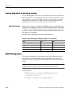
The baud rate selection as controlled by AM700 Boot Code is determined by the
setting of a pair of jumpers, J11 and J13, located on the CPU board. The jumper
settings are shown in Table 6–8. Serial ports are configured for 8-bits data, with
no parity, 1 stop bit, and Xon/Xoff flow control when transmitting (control_S to
stop, control_Q to continue).
Both ports will be initialized to run at the selected baud rate.
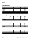
Table 6–8: Baud rate setting for diagnostic output to the serial ports
RATE J11 J13
38400 (factory setting) off off
9600 off ON
1200 ON off
19200 (default baud rate) ON ON
BOOT UP Diagnostics
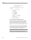
The following information is a description of the Power-up Diagnostics and is
provided to aid in troubleshooting a power-up diagnostic failure. Boot steps
signal their starting by writing the indicated signal value to the Diagnostic LED
display.
NOTE. Switch segment 2 of switch S3 on the CPU board must be in the UP
(OPEN) position to see these values on the Diagnostic LED display.
Signal values are:
All LED segments on for step 0, just after CPU reset instruction.
“1” through “F” for steps 1–15.
“0” through “.F” for steps 16–31 (currently ends at 19).
Baud Rate Selection