AM700 Audio Measurement Set Service Manual
3–1
Theory of Operation
A12
A2
A3
A1
A5
A9
A10
A7
A8
A13
A11
A4
A6
XLR
Digital
Audio
Analog
Acquisition
Audio
Generator
Front Panel
Keyboard
Touch
Panel
Sound
Headphones
Picture
Monitor
Floppy Disk Drive
1.44 Mbyte
Sample
Sample
Analog
Control Port
DSP
Serializer DMA
In
Out
CH A
CH B
CH A
CH B
Digital
Audio In
Audio Out
Host
Interface
4–Wire
Interface
68340
Front Panel
Pm
Serial
Interface
GPIB
PC Keyboard
Interface
Option
Board
Display
Main/CPU
Display Drive
Backlight
Inverter
Power
Supply
To All
At Keyboard
(optional)
Rear
Panel
Touch Screen
LCD Display
AC Mains
VGA Video
GPIB
COM 2
COM 1
Remote
DSP
In
Out
In
Out
In
Out
Unbal
Optical
AES Ref
Touch Screen
CRT
DMA
Blocks
Digital
Audio
Rear
Panel
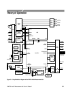
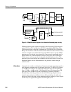
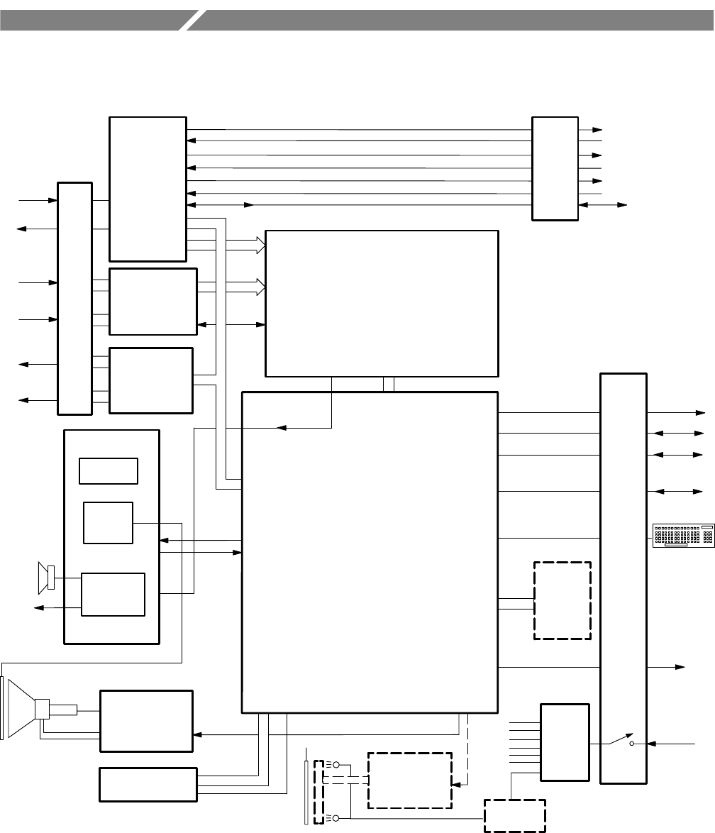
Figure 3–1: Simplified block diagram of the AM700 Audio Measurement Set


