Appendix A: Memory and Register Mapping
AM700 Audio Measurement Set Service Manual
A-13
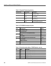
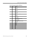
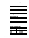
Table A-20: GPIB controller read registers
Address (hex) Register name
1600 0000 Int Status 0
1600 0004 Int Status 1
1600 0008 Address Status
1600 000C Bus Status
1600 0010 *
1600 0014 *
1600 0018 Cmd Pass Thru
1600 001C Data In
* The TMS9914A host interface data lines will remain in the high impedance state
when these register locations are addressed.
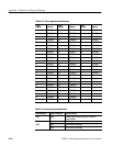
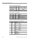
Table A-21: GPIB controller write registers
Address (hex) Register name
1500 0000 Int Mask 0
1500 0004 Int Mask 1
1500 0008 *
1500 000C Auxiliary Cmd
1500 0010 Address
1500 0014 Serial Poll
1500 0018 Parallel Poll
1500 001C Data Out
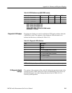
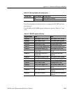
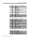
Table A-22: Port A memory map summary (DSP side)
Address (hex) Type Description
a. 1fff 0000 – 2000 FFFF R/W SRAM 128kx32 (default)
b. 1ffd 0000 – 2001 FFFF 256kx32
4000 0000 R DSP Board Status Register (DSR)
4100 0000 R/W DSP Board Program Register (DPR)
4200 0000 R/W Sample Receiver 0 Select
4300 0000 R/W Sample Receiver 1 Select
4400 0000 R/W Serializer Select
4500 0000 R/W Analog Interface Register (AIR)


