


Removal and Replacement Procedures
6–76
AM700 Audio Measurement Set Service Manual
on the rear panel of the chassis. The ribbon cable at J2 will have to be
reconnected if installing a new Display Monitor board. Otherwise it may
remain in place throughout the procedure.
5. Reroute and connect the Fan power wires to the Power Supply board at J11.
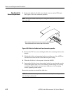
6. Reinstall the Touch Screen assembly. Do not touch the rear surface of the
touch screen. Keep it clean of fingerprints and dirt for reinstallation.
7. Line up the screw holes in the Touch Screen mounting bracket with the holes
in the mounting brackets on the front-panel casting.
8. Loosely install all four T-10 Posidrive screws, then press firmly on each
corner of the Touch Screen and tighten each screw so that the Touch Screen
is firmly against the back of the slotted alignment holes in the mounting
bracket. Then tighten each screw snugly.
9. Reinstall the Front Panel board, XLR bezel, and front-panel trim ring.
10. When reinstalling the front-panel trim ring, make sure the gasket around the
Touch Screen is not captured beneath the edges of the display area opening.
Use a blunt plastic tool to push back any area of the gasket that may be
under the edges of the front-panel trim ring.
1. Remove the cover. Refer to Cover Removal and Replacement on page 6–55
for more information.
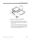
2. Remove the DSP board. Refer to DSP Board Removal/Replacement on page
6–69 for more information. Removing this circuit board eases the removal
and rerouting of the cables between the LCD flat panel and the display driver
board.
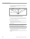
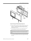
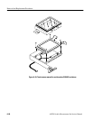
3. Take the protective front cover off and remove the two screws holding
front-panel trim ring to the instrument using a crosstip, P1 tip, screwdriver.
See Figure 6–38 for screw locations.
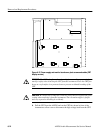
CAUTION. Use care not to damage the door to the disk drive when removing the
trim ring. Make sure the disk drive door is not caught in the slot in the trim ring
for the disk drive as you remove the trim ring.
4. Pull the bottom of the ring out away from the face of the instrument. Then
lift it slightly to clear the disk drive front and the top of the chassis casting
and remove the trim ring from the instrument.
5. Push out on the top of the Front Panel assembly from the inside of the
AM700 to release it from the chassis casting.
LCD Flat Panel Display
Assembly (A14)
Removal/Replacement