Diagnostics
6–44
AM700 Audio Measurement Set Service Manual
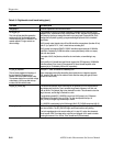
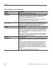
Table 6–11: Digital audio circuit board testing (cont.)
Test name Test description
Test group 2 Generator adjustments and functional checks.
2.6 adj_gen_pll
This is the pll that does jitter generation
and phase shift of the generator output.
This test locks the pll to 12.288 MHz. The
operator adjusts L5 to give correct vco
control voltage.
The generator pll consists of a phase comparator contained in U105, error amp U21B,
integrator U21A, resonant tank Cr9/L1 and oscillator IC U64. Jitter dac U103 changes the
lock phase by injecting an analog offset into the error amp input. Phase-shift PAL U104
changes the lock phase by putting a programmable digital phase shift in the feedback
loop divider.
U105 (pcomp) output signals at pins 25 and 26 should be narrow pulses (less than 20 ns)
with a 1.3 ms period. Pin 17, “slow”, should be low, saturating Q18.
U105 (pcomp) input signals PHMCK, PHWCK should be square waves at 12.288 MHz
and 48 kHz, respectively. PHCBL should be a narrow pulse (barely visible on a scope)
with a 40 msec period.
The output of U103, the jitter dac, should be dc at mid-scale, not contributing to any
offset.
U104 (pshift) pin 13 should be a legal ttl clock signal at the VCO frequency (12.288 MHz
if this test passes). Pins 14 and 15 are outputs of U104 and should be pulses at the
frequency of pin 13 divided by 256 and 16, respectively.
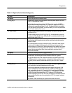
2.7 gen_pll_response
This test slowly toggles the frequency of
the input clocks to the generator pll
between 32kHz and 48kHz sample rates.
The operator checks the vco control voltage
at the output of U21 to see that the loop
re-locks at 48 kHz within 8 msec.
U105 pin 17, “slow”, should be low, saturating Q18.
Other components which affect the settling time include the error integrator capacitor,
C28, varactor CR9, and all of the resistors which affect the analog loop gain (all those
around U21A and U21B).
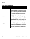
2.8 gen_pll_unlock_flag This test checks operation of the unlock flag for the generator pll. It first checks that the
flag indicates lock at 48 kHz. Then it switches the generator frequency to 32 kHz and
back to 48 kHz. The (latched) flag is then checked for unlock. The command to clear the
flag is then sent, and the flag is checked for re-lock.
The signal being tested (PH_UNLOCK) comes from U105 (pcomp) pin 6. Whenever
U105 thinks it’s unlocked, it sets pin 6 high. The high level persists until pin 16
(ER_CLEAR) is brought high momentarily to clear it.
PH_UNLOCK is read serially by the 56k through U94.3. ER_CLEAR comes from U96.15.
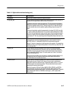
2.9 gen_pll_range This test checks the locking frequency range of the generator pll. It locks the pll to 25 kHz
first, then to 58 kHz. The PH_UNLOCK flag is read in each case to verify locking.
The lock range depends on the correct setting of L1 in step 2.6, and on the characteris-
tics of varactor CR9. The voltage at the output of error integrator U211 needs to be able
to swing from around –9 to +9 volts. “Slow” should be off (Q18 saturated).


