


Theory of Operation
3–26
AM700 Audio Measurement Set Service Manual
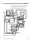
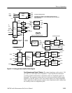
Frequency Offset (diagram 7)
The circuitry on this diagram allows tuning of the sample rate frequency. There
are two synthesizers in series to produce a wide range of frequencies with fine
resolution. The first synthesizer, U82, receives a clock frequency of approxi-
mately 8 to 12 MHz (12.228 MHz for a sample rate of 48 kHz). The synthesizer
devices have a built in phase comparator. A loop filter and following amplifier,
U39B, smooths the output of the synthesizer and drives the tuning varactor of
the oscillator, U78. The oscillator output is fed back to the phase comparator of
the first synthesizer and to an inverting amplifier, Q4. This amplifier converts the
ECL level of the oscillator to a level of approximately 1.5 V p-p to drive the
second synthesizer, U82.
The second synthesizer circuit is similar to the first with a loop filter and
amplifier that drives a varactor in the second oscillator, U79. That oscillator
output is fed to a current-to-ttl converter, Q14 and Q15, which produces
complementary OFFSET and (OFFSET) output signals used for interface clock
generation.
A/D, Frequency/Phase Counter, and Power Distribution (diagram 8)
The circuitry on this diagram covers several unrelated areas of the Digital Audio
board. The A/D Converter, U137, is used to provide the values of equalization
level and the AGC gain level back to the Serial Control PAL. From there, these
values are read back to the DSP for use in the various measurements that require
them for making calculations, one of those being the peak-to-peak amplitude of
the input signal, for example.
These programmable counters, U139 and U140, are usually programmed to
count the number of master clocks during a given interval. They may be used to
provide a number for measuring the absolute frequency of the master clocks or
the relative frequency difference between a reference and the master clock. These
PALs also generate the SLOW CLOCK signal and the (DSPRST) signal.
Several voltage regulators are shown in this diagram. They are the on-board
regulators for the +12 V, –12 V, +5 V, –5 V, and –8 V sources. The input power
for these regulators is obtained from the +15 V and –15 V sources which are also
supplied to the Digital Audio board.
A +5 V reference source is developed by U138. This reference is used to produce
two difference reference levels to the A/D converter, U124, that is part of the Eye
Sampler circuit, shown in diagram 11.
Frequency/Phase
Counters
Power Distribution