


Theory of Operation
AM700 Audio Measurement Set Service Manual
3–29
Rear Panel Board (A4)
PUSH
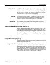
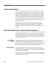
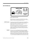
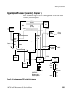
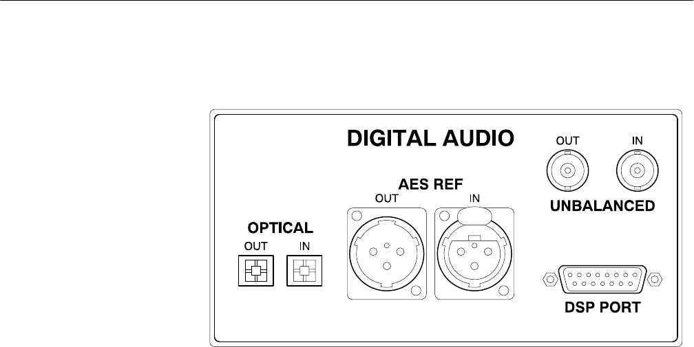
Figure 3–8: Digital audio connectors
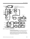
The Rear Panel board seen in Figure 3–8 is schematically shown in a single
diagram (A4, diagram 1). All the digital audio rear panel connectors interface to
a single 32 pin connector and cable to the Digital Audio board.
The rear panel board provides the interconnections for the various methods of
connecting digital signals in and out of the AM700. These are: OPTICAL IN and
OPTICAL OUT, AES REF IN and AES REF OUT, UNBAL AES IN and
UNBAL AES REF OUT, and the DSP I/O port connector.
The TOSLINK optical connectors contain transducers to convert light to a
TTL-level electrical signal and electrical to light for the in and out connectors
respectively. The AES REF IN and OUT are standard XLR connectors, fed
through isolation transformers. For the UNBAL AES REF IN and OUT, the
connectors are BNC. All the input and output lines are filtered to reduce EMI
effects on the signal lines.
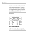
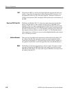
The user may connect a compatible digital microphone or other compatible
digital signal source directly to the DSP for processing through the DSP Port
connector (pinout shown in Figure 3–9). When the AM700 is receiving data, the
external device supplies the Bit Clock, Frame Clock, and Receive Data. When
sending data, the AM700 supplies Transmit Data that is synchronized with Bit
and Frame Clocks of the external device. Rate 0, Rate 1, Rate 2, Flag 0, and Flag
1 are reserved for future use. The external device may be powered by the + and
–12 V sources provided from the DSP Port connector. These sources are current
AES REF Connectors
DSP PORT