


Removal and Replacement Procedures
6–82
AM700 Audio Measurement Set Service Manual
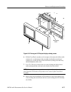
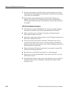
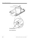
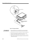
1. Place the LCD assembly on the rear shield and align the holes at the corners
with the standoffs on the rear shield. Note that the touch screen cable is
routed beneath the flat panel display.
2. Reinstall the four screws at the corners and evenly tighten them.
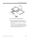
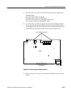
3. Replace the touch screen with metal frame over the LCD panel. On the
earlier versions of the touch screen, use care to keep the touch screen cable in
the slot in the metal frame so as not to pinch it between the metal frame and
the rear shield. For the later version display assemblies, make sure the
backlight leads do not get pinched by the touch screen metal frame when you
reinstall it.
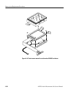
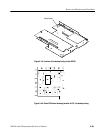
4. Guide the cables of the LCD assembly through the housing and align
mounting holes of the replacement LCD assembly with the screw holes in
the front casting.
5. Attach the LCD assembly to the front casting using four screws. Align the
assembly parallel with the top and bottom of the front casting and tighten the
screws evenly.
6. Route the cables to the display driver board as noted in step 9 of the
preceding procedure, and reconnect them to the Display Driver board.
7. Replace the cable retaining bracket using two screws.
8. Position the front panel assembly in the front-panel casting and reconnect the
touch screen connector at J4 on the front panel board, the front panel ribbon
cable connector to J50 on the CPU board, and the headphone cable connector
at J6.
9. Press the front panel assembly into the chassis casting to firmly seat it in the
grounding fingers around the edge.
10. After reinstalling the Front Panel assembly into the front-panel casting, if
you have removed the XLR bezel reinstall it now. Do this by tipping the
XLR bezel up to slip it over the PUSH release levers on the XLR connectors.
Then rotate the XLR bezel downward to snap it gently into place with the
top edge grips under the edge of the Front Panel.
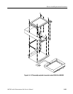
11. Place the top of trim ring over the top of the front-panel casting, align it with
the disk drive housing, and press the trim ring into place so that it snaps into
place on the top of the front-panel casting. Install the two crosstip P1 screws
that hold it on to the front-panel casting.
12. Place the AM700 bottom down.
13. Replace the DSP board.
14. Reconnect the ribbon cable (at J1) to the DSP board.
Replacing the LCD
Assembly