


Theory of Operation
3–8
AM700 Audio Measurement Set Service Manual
frequency. The notch has a Q of 2.7 and a depth of greater than 20 dB throughout
its 20 kHz tuning range.
Test points, TP11 for CHB and TP12 for CHA, are provided for viewing the
signal at the output of the notch filter. Analog ground is available at TP10.
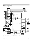
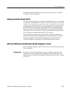
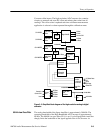
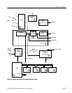
A/D Converters (diagram 4)
Channel A and Channel B of the High Resolution A/D Converter are identical in
operation as are Channel A and Channel B of the High Bandwidth A/D
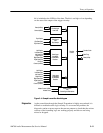
Converter. Figure 3–3 is a simplified diagram of the Channel A A/D Converter.
Refer to schematic diagram 4 of the A1A1 circuit board for the following circuit
description.
In the input to the High Resolution A/D Converter, a unity-gain buffer, U45A
and + and –5 V clamp isolates the input of the A/D converter from the output of
the Input Amplifier (or notch filter) and prevents overload of the A/D Converter
IC.
The anti-aliasing low pass filter, U60B, is a 3-pole, bessel filter. The 3 dB roll-
off point is at 150 kHz so within the 24 kHz bandwidth of interest there is
minimal phase shift.
The output of U60B is fed to the plus input of U58, the High Resolution A/D
Converter. It is also fed to the inverting (minus) input of U60A, a unity-gain
inverting buffer. The output of this state provides the negative differential side of
the input signal to the A/D Converter.
The High Resolution A/D Converter, U58, is a two-channel delta-sigma
converter. Both Channel A and Channel B differential signals are applied to the
converter inputs. The analog input signal is converted to a serial digital data
stream with a L/R output signal provided to indicate to following devices when
the data applies to the left channel and when it applies to the right channel. The
A/D Converter also outputs a serial clock (1SCLK) used to synchronize the High
Resolution output data into the Sample Transmitter (diagram 5). The High
Resolution analog data is 64 times oversampled.
The Offset DAC, U81, converts serial digital data to analog output voltages on
its outputs. During calibration, the amount of offset seen in the analog channels
is measured. That measurement determines a calibration constant used to derive
the offset correction voltages to the A/D Converters. In the High Resolution A/D
Converters, that offset is applied to the 150 kHz anti-aliasing filters. The offset
corrections for the High Bandwidth A/D Converter are applied to the A/D
Input Buffer and 5 V
Clamp
Anti-Aliasing Low Pass
Filter
Single-ended to
Differential Converter
High Resolution A/D
Converter
Offset DAC