


Theory of Operation
3–70
AM700 Audio Measurement Set Service Manual
Input, Inverter, and Regulators (diagram 1)
The following circuit descriptions follow the schematic diagrams and indicate
the circuit components of the circuitry. Refer to schematic diagram 1 of the A11
power supply board for the following description.
The AC mains voltage is applied to the preregulator power rectifier through a
Line Filter (FL1), Fuse F1, and the Master Power Switch (S1) on the rear panel
of the instrument. A bleeder resistor, R3, is placed across the input filter to
discharge the filter capacitors when AC power is removed. The inrush of turn-on
current is controlled by surge suppressor RT1. MOV RV1 and RV2 reduce noise
spikes and help protect the input circuitry from a major overload in the event that
an incorrect mains voltage is applied when the power supply is set to operate on
115 Vac. A spark gap device, E1, also acts to protect the circuitry that follows it
by firing and causing the input fuse to open in the event of a major overvoltage.
As a warning, neon indicator DS1 blinks when the primary power is up.
Common-mode EMI filtering of the rectified voltage is provided by L3, C10,
C11, C12, C13, and C14. Resistors R7 and R8 provide damping for the
inductance of L3.
The Line Selector switch, S2, converts the power supply from a bridge rectifier
for 230 V operation to full-wave doubler for 115 V operation. When the Line
Selector is set for 230 VAC operation, diode bridge CR1 is a conventional bridge
rectifier. For 115 VAC operation, the top two diodes of CR1 and filter capacitors
C7 and C8 act as a full-wave voltage doubling circuit. The rectified voltage is
applied across both C7 and C8 on alternate half cycles of the input voltage. The
output voltage is then taken across them in series so the output voltage is the
sum of the voltages across each capacitor. The output voltage for either 115 V or
230 V operation is approximately 300 VDC. Bleeder resistor R5, across the filter
capacitors, drains the capacitor charge when power is removed.
The switching action of S2 also switches the primary winding of T1 to produce
the same voltage output from the secondary winding for either line voltage
position to the housekeeping supply. For 115 V operation, the two primary
windings are in parallel, and for 230 V operation the two windings are in series.
Jumper J2 is for testing purposes only. Troubleshooting should be attempted only
by an experienced service person. Jumper J2 may be pulled to disconnect the
input rectifier from the switching power supply. This permits a service person to
determine if the input rectifier and regulator circuitry are functioning correctly
without the load.
PWM U1 is a pulse-width modulated, current-mode controller that drives the
preregulator stage. The preregulator is controlled by the output of the +5 V
supply. This makes +5 V the regulated output; the other voltages (–16.5 V,
+16.5 V, –22 V, and +22 V) are set by the turns ratio of T5. The PWM uses the
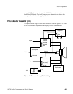
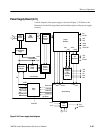
Input Power
115 V/230 V Input
Switching
Pulse-Width Modulator
and Control Circuits