Theory of Operation
3–44
AM700 Audio Measurement Set Service Manual
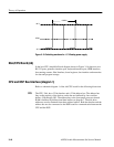
+22 V
–16 V
A Gnd
[50 kHz
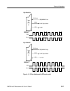
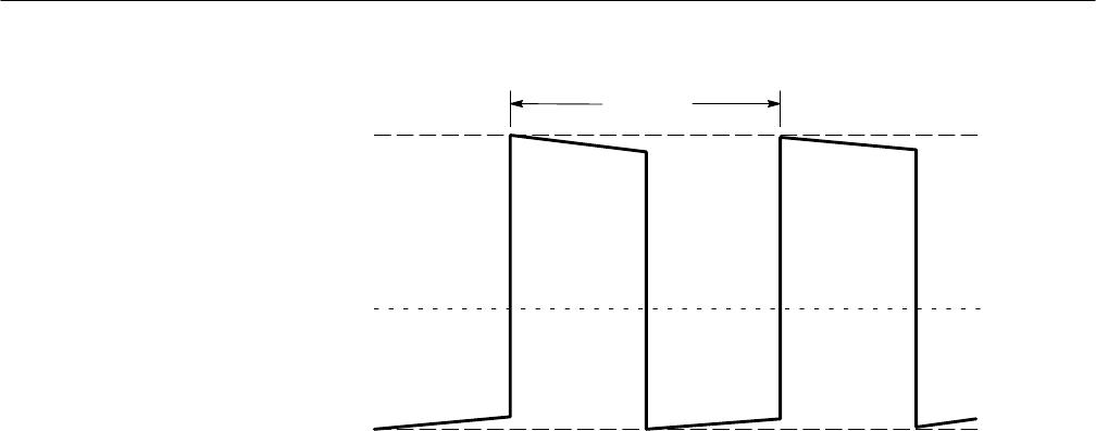
Figure 3–15: Switching waveform for –15 V floating power supply
Main/CPU Board (A6)
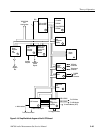
In the host CPU (simplified block diagram shown in Figure 3–16) there are two
RS-232 ports, generator interface port, keyboard interface port, GPIB interface,
free running counter, Host Interface, board registers, bus interface and memories
for data and program storage.
CPU and DSP Bus Interface (diagram 1)
Refer to schematic diagram 1 of the A6 CPU board for the following discussion.
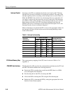
The CPU, U64, has a 32 bit data bus and a 32 bit address bus. The address bus
lines to the majority of the devices on the bus are buffered by four octal bus
buffers, U80 through U83. The address bus to the front panel processor shared
RAM is buffered by bidirectional data buffers on diagram 7. The disk drive
addresses are also obtained from these address buffers. Both the data bus and the
address bus are also connected to the DSP board for communication between the
CPU and the DSP.
CPU


