


Specifications
AM700 Audio Measurement Set Service Manual
1–9
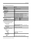
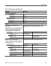
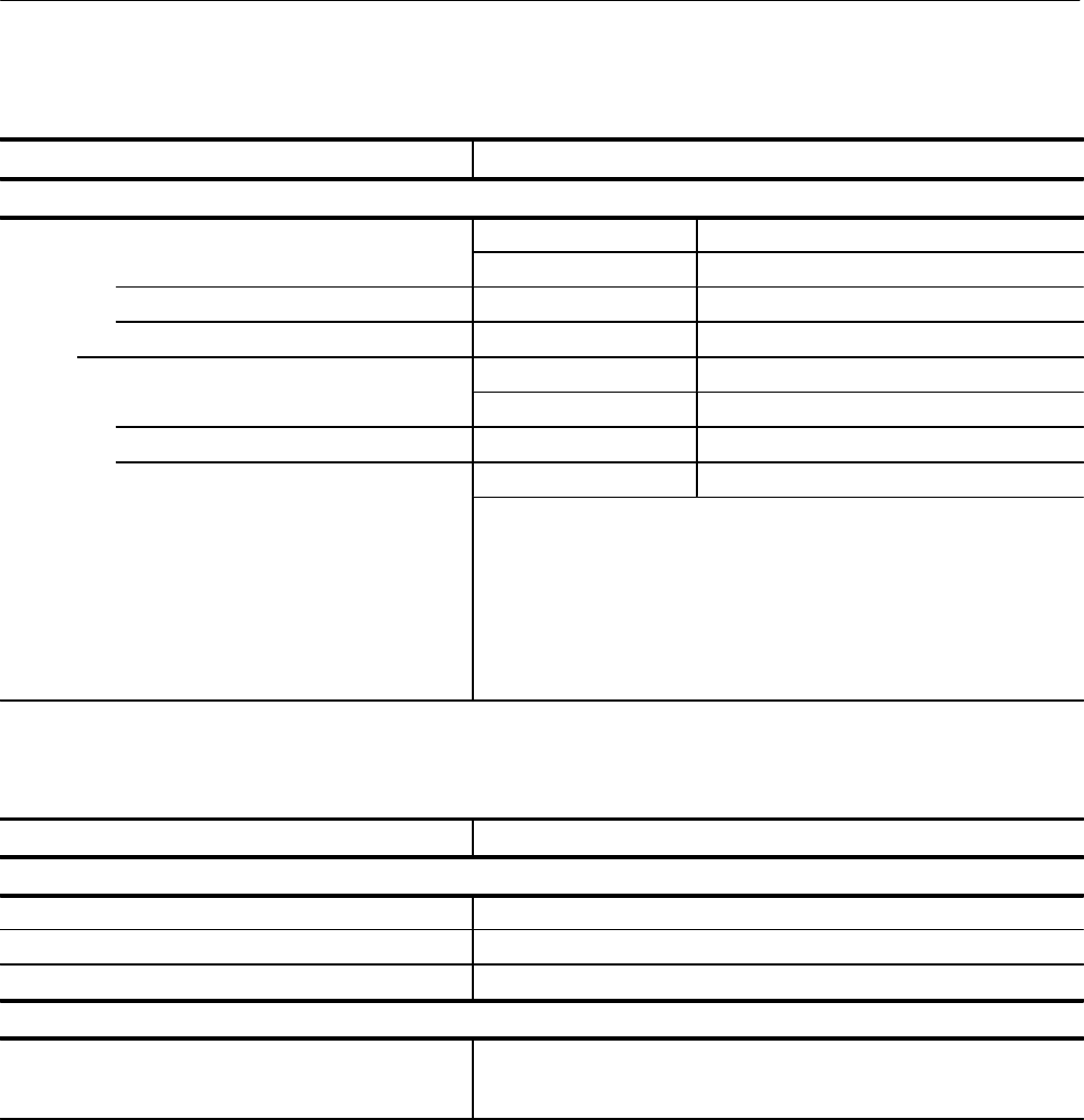
Table 1–2: Analog analyzer specifications (cont.)
Capabilities Description
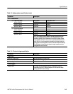
THD + N measurement
On –4 dBu Input Range At Full Scale At Full Scale –6 dB
400 Hz to 6.6 kHz ≤0.003% ≤0.006%
100 Hz to <400 Hz ≤0.0075% ≤0.006%
20 Hz to <100 Hz ≤0.0125% ≤0.0075%
On –10 dBu Input Range
400 Hz to 6.6 kHz ≤0.005% ≤0.010%
100 Hz to <400 Hz ≤0.0075% ≤0.010%
20 Hz to <100 Hz ≤0.015% ≤0.011%
THD + N is limited by the A/D distortion (primarily 3rd harmonic) near
full-scale at frequencies below 200 Hz. At –6 dB relative to FS, the
increase in distortion at low frequencies is much less, typically 0.003%
versus 0.0075% (FS) at 20 Hz. Under some conditions (measurements
below 200 Hz), it may be desirable to manually set the input range one
setting higher, sacrificing 6 dB of noise floor for better distortion readings.
The auto-range circuitry optimizes dynamic range, somewhat compro-
mising distortion near full-scale.
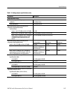
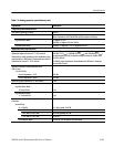
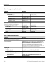
Table 1–3: Electronic trigger specification
Capabilities Description
Trigger input
Number of Trigger Inputs One input located on the rear panel.
Electrical Characteristics TTL-level, Schmitt-trigger input.
Connector Type BNC female
Psuedo triggers
Trigger Events Two trigger events may be generated by remote control using the
commands in the SCPI TRIGger subsystem: STARt starts the sweep
running and STOP ends the sweep.