


Removal and Replacement Procedures
AM700 Audio Measurement Set Service Manual
6–71
Reverse the procedure to reinstall the Front Panel assembly.
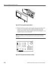
5. Position the Front Panel assembly in the front-panel casting and reconnect
the touch screen connector at J4 on the Front Panel board, the Front Panel
ribbon cable connector to J50 on the CPU board, and the headphone cable
connector at J6.
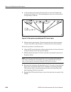
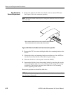
6. After reinstalling the Front Panel assembly into the front-panel casting,
reinstall the XLR bezel. Do this by tipping the XLR bezel up to slip it over
the PUSH release levers on the XLR connectors. Then rotate the XLR bezel
downward to snap it gently into place with the top edge grips under the edge
of the Front Panel.
7. Place the top of trim ring over the top of the front-panel casting, align it with
the disk drive housing, and press the trim ring into place so that it snaps into
place on the top of the front-panel casting. Install the two crosstip P1 screws
that hold it on to the front-panel casting.
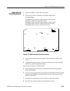
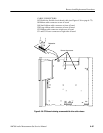
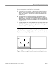
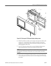
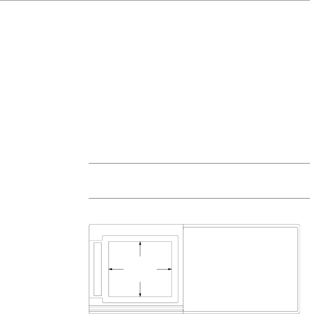
NOTE. Make sure the gasket around the Touch Screen is not captured beneath the
edges of the display area opening in the trim ring. Use a blunt plastic tool to
gently push back any area of the gasket that may be caught under the edges of
the front-panel trim ring (see Figure 6–35).
Figure 6–35: Touch screen gasket precaution areas when Installing the trim ring