Theory of Operation
AM700 Audio Measurement Set Service Manual
3–19
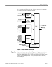
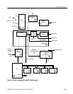
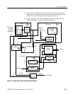
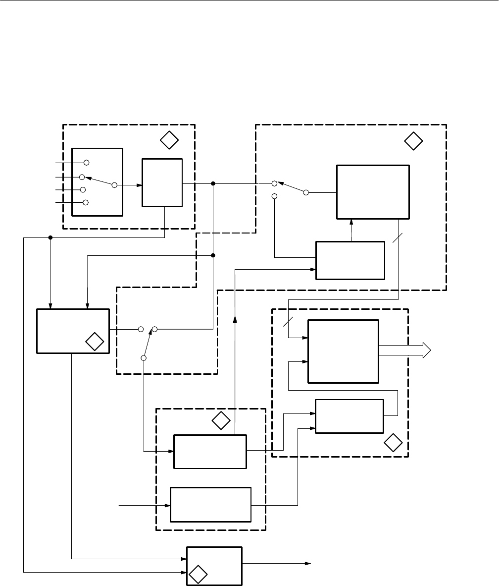
H Data formatter. The Data Formatter creates the start and stop bits for the
serial data from the AES Decoder. These bits control the formatting of the
serial data into parallel data bytes in the Sample Transmitter.
H Sample transmitter. The sample transmitter arranges the serial data into
eight-bit data bytes to be sent to the DSP circuit board.
6
11
12
3
9
8
3
3
From Generator
XLR (Front)
BNC (Rear)
Optical (Rear)
XLR (Rear)
In Source
Auto
Main Decoder
Reference
ADC
Data
Sample
U101
U102
U86
U87
U137
U109
U110A,
AGC
Source Select
Eye/Jitter
U130
U113A,U122,
Sample PLL
Eye
Phase
Eye SourceEQ Out
EQ In
Gain
Gain
EQ Level
TRI SRD
To Serial Control
AES1
AES2
To DSP
Eye Sampler
Eye Source
Input
U111,
U112A
Equalization
Decoder
Transmitter
Formatter
Sample
Transmitter
U123,Q16,Q17
Error
Sampler
Figure 3–7: Digital audio receiver simplified block diagram


