


Specifications
1–22
AM700 Audio Measurement Set Service Manual
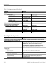
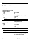
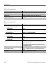
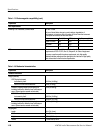
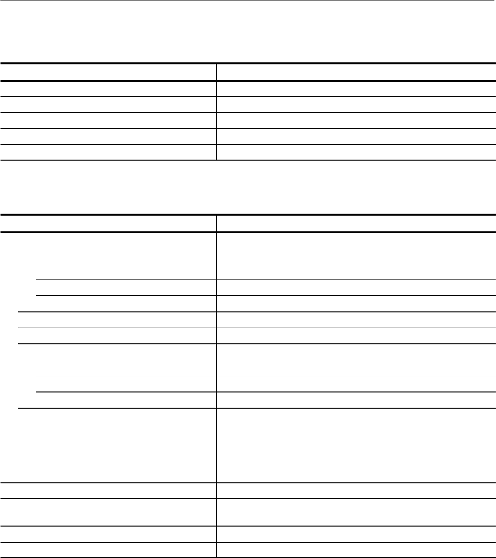
Table 1–10: Front panel hardware
Capabilities Description
Analog Audio Standard XLR female. Pin 1 shield, pin 2 is +, pin 3 is –
Digital Audio Input: XLR female, Output: XLR male
Headphone Jack Standard 1/4 inch, stereo; channel A is left, channel B is right
Headphone Nominal Impedance 8 to 2000 W
Output Power to Headphones 20 mW minimum into 8 to 2000 W headphones at full volume
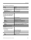
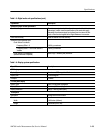
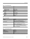
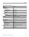
Table 1–11: Rear panel hardware
Capabilities Description
Remote Connector Female DB9
Normally Open Contact, Pin 3 to Pin 9
Maximum Voltage 28 VDC
Maximum Current 500 mA
Maximum Power 14 W
Relay Closure Input Pin 1 Pulled to +5 V ≤100 mA; input is protected
Ground Pins 2, 4, 6, and 8
Normally Closed Contact, Pin 5 to Pin 9
Maximum Voltage 28 VDC
Maximum Current 500 mA
Maximum Power 14 W
+5 V Output, Pin 7 + 5 V @ 5 mA
Use ground pins 2, 4, or 6 to pull the relay-closure input low through an
external contact-closure relay.
The +5 V output is provided to drive the relay-closure input pin through an
external contact-closure relay.
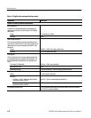
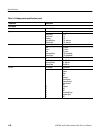
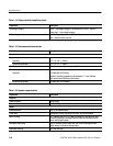
GPIB Connector Meets electrical specifications described in IEEE–488
COM1 and COM2 Connectors DB9 male, configured as RS–232C, DTE; provides connection for serial
printers
VGA Connector DB15 female; supports external VGA monitor
Keyboard Connector Supports AT-type keyboard