


Adjustment Procedures
AM700 Audio Measurement Set Service Manual
5–11
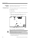
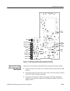
Display Monitor Adjustment (for CRT display monitor)
The following adjustment steps are used to align the CRT display. These
adjustments include those needed for factory service alignment after repairs to
the display monitor module and a shorter procedure for alignment of the installed
display monitor.
Use the procedures in the Remove and Replacement Procedures in the Mainte-
nance section beginning on page 6–73 to remove the display monitor assembly
for repair and reinstallation. Use the long adjustment procedure after the repaired
display monitor is reinstalled, especially for a replacement of the CRT or
deflection yoke.
For a normally operating installed display monitor assembly, perform the
verification procedure of the CRT display (Verify CRT Display Operation on
page 4–33) to determine the extent of adjustment needed, if any. Use the shorter
adjustment procedure on page 5–18 to make minor adjustments to the CRT after
a verification check indicates the need for adjustment. Make only those
adjustment needed to align the display monitor assembly.
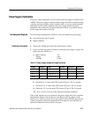
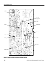
4. The following tools are required during the CRT display adjustment for a
complete CRT alignment after changing the CRT, the deflection yoke, or the
display monitor circuit board.
H Video source interconnection cable
H VGA Distribution amplifier.
H Photometer
H CRT test graticule
H Geometry correction magnets
Blue 119–1616–00 (strongest)
Green 119–1863–00
Red 119–1615–00
Yellow 119–4341–00
H Clear RTV silicone adhesive (for magnet attachment)
H 0.1 inch spacing shorting jumper
H Test oscilloscope
H Small flat head screw driver for adjustments
H 3.5 inch diskette with the Tektronix CRT test pattern file.
H Personal computer with 3.5 inch floppy disk drive.
Test Equipment Required