


Performance Verification
4–48
AM700 Audio Measurement Set Service Manual
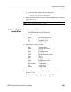
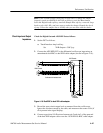
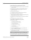
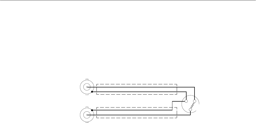
shown in Figure 4–20 to make the connection from the XLR connector to the
oscilloscope inputs.
5. Measure the terminated-output level using the oscilloscope.
6. Calculate the ratio of the input-terminated level to open-circuit level.
7. Check that this ratio is in the range of 0.45 to 0.55.
1
2
3
110W
BNC Female
XLR Female
Cable used is insulated coax.
Figure 4–20: Dual BNC to 110 XLR female adapter cable
8. Measure the terminated-output level.
9. Calculate the ratio of the input-terminated level to open-circuit level.
10. Check that this ratio is in the range of 0.45 to 0.55.
11. Connect the front panel Digital Out signal to the differential oscilloscope
input using a non-terminating adapter.
12. Repeat step 3 through step 10 for the Digital Out signal.
Check the Digital In and AES REF In impedance as follows:
1. Record the terminated Digital Out signal level measured by the oscilloscope.
2. Remove the precision termination and connect the free end of adapter to the
Digital In connector.
3. Measure the signal level with the oscilloscope.
4. Calculate the ratio of the input-terminated level to the precision-terminated
level.
5. Check that this ratio is in the range of 0.95 to 1.05.
6. Repeat the check for the AES REF In connector.