


Theory of Operation
3–56
AM700 Audio Measurement Set Service Manual
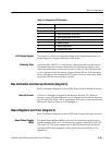
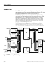
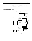
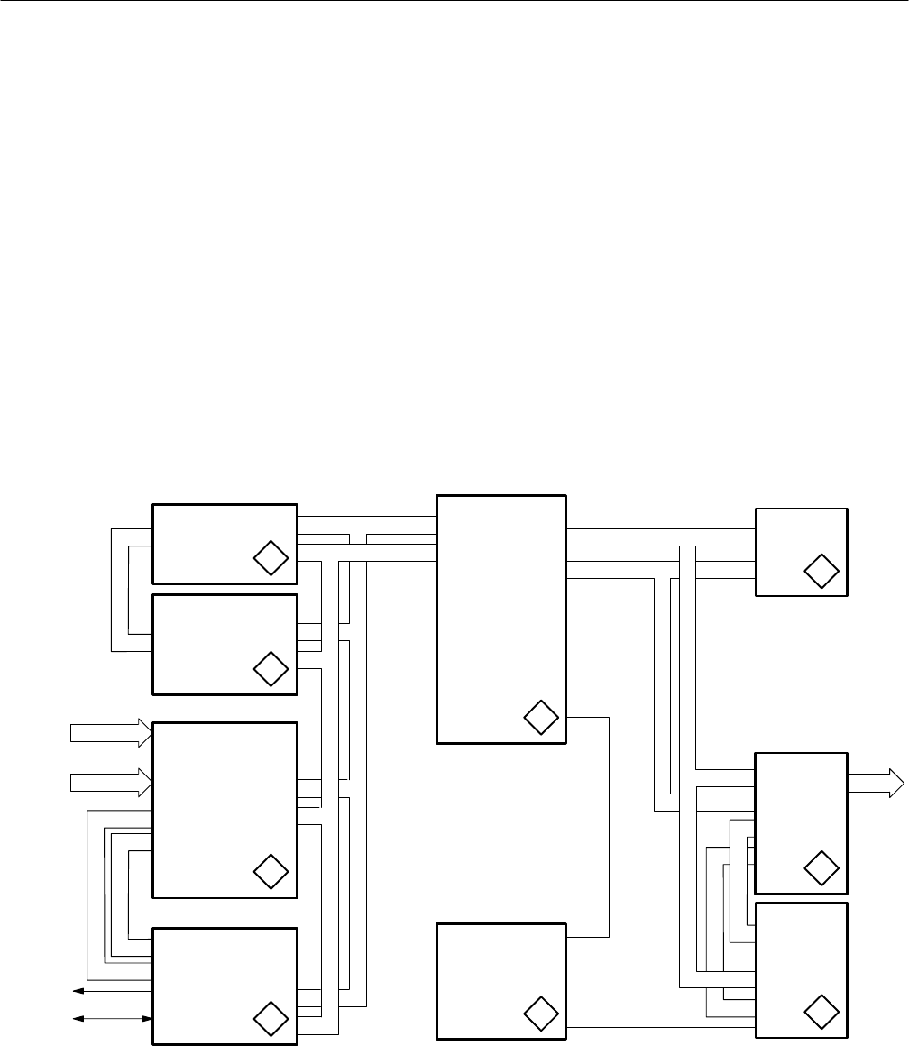
DSP Board (A7)
In the DSP board circuitry, there are local registers, an analog interface port, a
DMA interface, and fast static memories that reside in the processor’s port A and
port B buses. A simplified block diagram is shown in Figure 3–17.
The DSP (digital signal processor) accepts digital data (the digitized analog
signal inputs) from either the Digital or the Analog input boards through sample
transmitter/receiver ASICs. Communication with the Main/CPU is through a
DMA ASIC. The digitized audio signal is serialized and converted to analog
signals for driving the front panel headphone circuit. Control circuitry on the
DSP circuit board provides signals to set up the acquisition gain, bandwidth,
filters, etc., on the Analog Acquisition board.
The DSP has port A and port B memories to handle the processed data and
commands. Instructions to the DSP are written to the Port B memory by the
CPU. The DSP then runs the programmed instructions from the Port B memory.
Port A Memory
RX ASIC
RST40
RSTH
21
RX ASIC
AN0[0 – 3]
4
5
6
8
BA[0 – 31]
BD[0 – 31]
7
3
LADR[0 – 31]
Digital Data
Analog Data
Front Panel
DSP/CPU
Interface
ASIC
DMA ASIC
CPU
Reset
and
Clocks
Serializer
7
Analog Port
Control
Sound
Bus Buffer
and
Connectors
Sample
Receiver
DSP
Board Registers
Bus Arbitrator
ANI(0 – 3)
Analog
Acquisition
Port B
Memory
Audio Serializer
DA(0 – 31)
ADRA
(0 – 31)
Figure 3–17: DSP board simplified block diagram