Removal and Replacement Procedures
6–58
AM700 Audio Measurement Set Service Manual
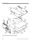
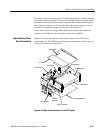
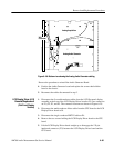
A7 DSP
A6 Main/CPU
A12 Disk drive
A13 LCD
Display Driver
A4 Rear panel
A3 Digital audio
A11 Power supply
A1 Analog acquisition
A2 XLR Connector
A5 Audio
generator
A9 Front panel
A14 Flat panel
display assembly
Figure 6–23: Major module locations for the LCD flat panel display
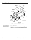
1. Place the AM700 top down.
2. On the Audio Generator board, disconnect the power cable at J16 and the
ribbon cable at J17 so that the Analog Acquisition board may be removed.
Analog Acquisition (A1)
Removal/Replacement


