Removal and Replacement Procedures
6–64
AM700 Audio Measurement Set Service Manual
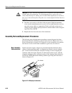
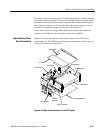
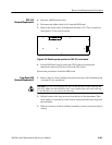
1. Remove the four T15 Torx screws the hold the rear panel assembly to the
main chassis.
2. Pull the rear panel assembly out of the recess far enough to disconnect the
ribbon cable from the rear panel connector, J2, and extract the assembly.
3. Reverse the procedure to reinstall the Rear Panel assembly.
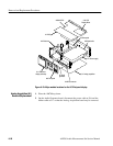
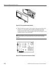
1. Place the AM700 top down.
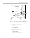
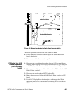
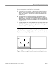
2. Disconnect all cables connected to the Analog Audio Generator board. The
cable locations are shown in Figure 6–28.
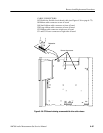
CABLE CONNECTIONS:
Analog Acquisition to Analog Audio Generator
J30 to J14
J29 to J13
Analog Audio Generator to XLR Connector
J8 to J9
J9 to J8
Analog Audio Generator to CPU board
J17 to J53
Analog Audio Generator to Power Supply
J16 to J7
The LCD Display version of the AM700 has a additional interconnection
cable from the floating power supply (now in the power supply module) to
the Analog Generator board. Disconnect the floating power supply cable
connector.
3. Remove the eight screws securing the board with a T-15 Torx screwdriver.
Rear Panel (A4)
Removal/Replacement
Analog Audio
Generator Board (A5)
Removal/Replacement


