Removal and Replacement Procedures
AM700 Audio Measurement Set Service Manual
6–59
J13
J14
J29
J30
J1
J2
J27
J28
J17
J16
Analog Audio Generator
Analog Acquisition
XLR
Connector
J26
Trigger Input
Connector
Remove this
standoff post
J25
Hybrid
retaining
clip
J10
J11
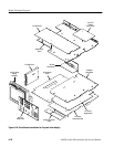
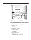
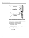
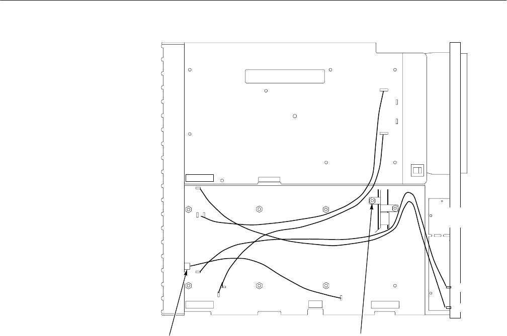
Figure 6–24: Bottom view showing the connections to the Analog Acquisition board
3. Disconnect all cables connected to the Analog Acquisition board.
CABLE CONNECTIONS:
Analog Audio Generator to Analog Acquisition
J13 to J29
J14 to J30
Analog Acquisition to XLR Connector
J1 CHB (the shorter cable)
J2 CHA (the longer cable)
Analog Acquisition to Trigger Input Connector
J28 (a white cable)
Power and Signal Interconnections
J25 Power cable connector
J27 Ribbon cable connector near rear of board
J26 Ribbon cable connector near front of board.


