


Theory of Operation
AM700 Audio Measurement Set Service Manual
3–51
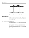
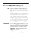
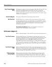
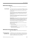
Table 3–2: Diagnostic LED Definitions
LED Description
0 reserved
1 reserved
2 on : Flash EPROM (bank 0) not found
3 on : Flash EPROM (bank 1) not found
4 on : Flash EPROM (bank 2) not found
5 on : DRAM not found
6 on : battery supply failure
7 on : hardware reset active
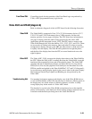
This register is a write only octal latch which can be programmed to turn on or
off the diagnostic 7-segment LED on the CPU board.
A monitor chip, a DS1232, is used monitor software execution on the host bus.
The monitor chip has an interval timer that forces the time-out signal to active
state if the strobe input is not driven low prior to time-out. The watchdog timer
is set to operate on time-out settings of approximately 600 ms. If the watchdog
timer is allowed to time-out, then the TEA signal is driven to active state which
signals the CPU that a bus error has occurred.
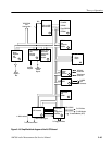
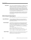
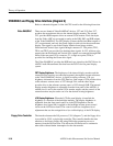
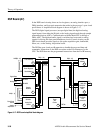
Bus Arbitration and Interrupt Encoder (diagram 5)
Refer to schematic diagram 5 of the A6 CPU board for the following discussion.
All levels of interrupts are applied to the Interrupt Encoder, U51. When an
interrupt occurs, U51 determines the level of interrupt and encodes the interrupt
signals to the CPU (IPL0 – IPL2) appropriately. The source of the interrupts and
their level is shown in Table A-12 of Appendix A.
Board Registers and Timer (diagram 6)
Refer to schematic diagram 6 of the A6 CPU board for the following discussion.
The Board Status Register (BSR) is one of the two hardware registers used to
indicate hardware status. It is a 32-bit read-only register composed of U85, U87,
U90, and U126. The register outputs are on the CPU data bus and can only be
read by the CPU. Bit assignments for the register are given in Table A-13 in
Appendix A.
LED Display Register
Watchdog Timer
Interrupt Encoder
Board Status Register
(BSR)