


Appendix A: Memory and Register Mapping
AM700 Audio Measurement Set Service Manual
A-11
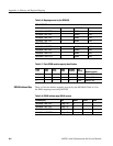
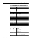
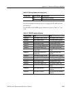
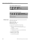
Table A-16: Interrupt inputs and sources (cont.)
Interrupt input Interrupt sourceType of interrupt
level Sample Receiver 0 Interrupt
level Sample Receiver 1 Interrupt
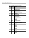
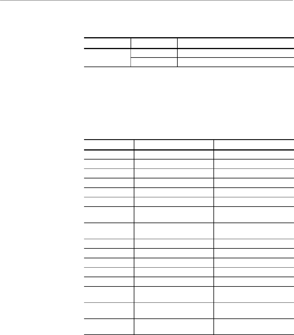
The following additional tables are for use in mapping the DUARTs and other
port interfaces.
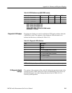
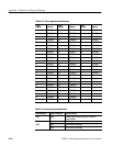
The DUARTA and DUARTB register addresses are given in Tables A-17 and
A-18.
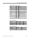
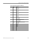
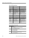
Table A-17: DUARTA register addresses
Register address Read Write
$10000000 Mode Register A (MR1A, MR2A) Mode Register A (MR1A, MR2A)
$10000004 Status Register A (SRA) Clock Select Register A (CSRA)
$10000008 Do Not Access Command Register A (CRA)
$1000000C Receiver Buffer A (RBA) Transmitter Buffer A (TBA)
$10000010 Input Port Change Register (IPCR) Auxiliary Control Register (ACR)
$10000014 Interrupt Status Register (ISR) Interrupt Mask Register (IMR)
$10000018 Counter Mode:Current MSB of
Counter (CUR)
Counter/Timer Upper Register
(CTUR)
$1000001C Counter Mode:Current LSB of
Counter (CLR)
Counter/Timer Lower Regis-
ter(CTLR)
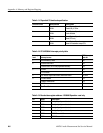
$10000020 Mode Register B (MR1B, MR2B) Mode Register B (MR1B, MR2B)
$10000024 Status Register B (SRB) Clock Select Register B (CSRB)
$10000028 Do Not Access Command Register B (CRB)
$1000002C Receiver Buffer B (RBB) Transmitter Buffer B (TBB)
$10000030 Interrupt Vector Register (IVR) Interrupt Vector Register (IVB)
$10000034 Input Port (Unlatched) Output Port Configuration Reg
(OPCR)
$10000038 Start Counter Command Output Port Reg (OPR) Bit Set
Command
$1000003C Stop Counter Command Output Port Reg (OPR) Bit Reset
Command