


Appendix A: Memory and Register Mapping
A-2
AM700 Audio Measurement Set Service Manual
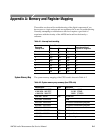
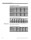
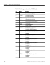
Table A-2: System memory map summary (host CPU side) (cont.)
Address (hex) DescriptionType
1300 0000 R/W Board Program Register
1400 0000 R Dip Switch
1500 0000 – 15xx xxxx W GPIB Write Register
1600 0000 – 16xx xxxx R GPIB Read Register
1700 0000 – 17xx xxxx R/W Real Time Clock Registers
1800 0000 – 18xx xxxx W LED Register
1900 0000 – 19xx xxxx R/W DSP-CPU Interface ASIC Select
1A00 0000 R 32-bit Counter
1B00 00xx R/W Generator Board Host Interface
1B80 00xx R/W Digital Audio Board Host Interface
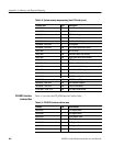
2000 0000 – 20xx xxxx R/W FEPROM
3000 0000 – 30xx xxxx R/W DRAM 4MB, 8 MB, 16 MB
40B2 0980 W 4/8 MB SIMM DRAM Register
42B2 0980 W 16 MB SIMM DRAM Register
5100 0000 R/W ONCE Data Read/Write Register
5200 0000 R ONCE Status Register
5300 0000 R/W ONCE Control Register
6000 0000 – 6000 0xxx R/W Host Interface Registers
7000 0000 – 70xx xxxx R/W Flash EPROM Board
CC00 0000 – CC0F FFFF R/W DSP DMS DRAM Access
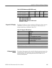
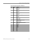
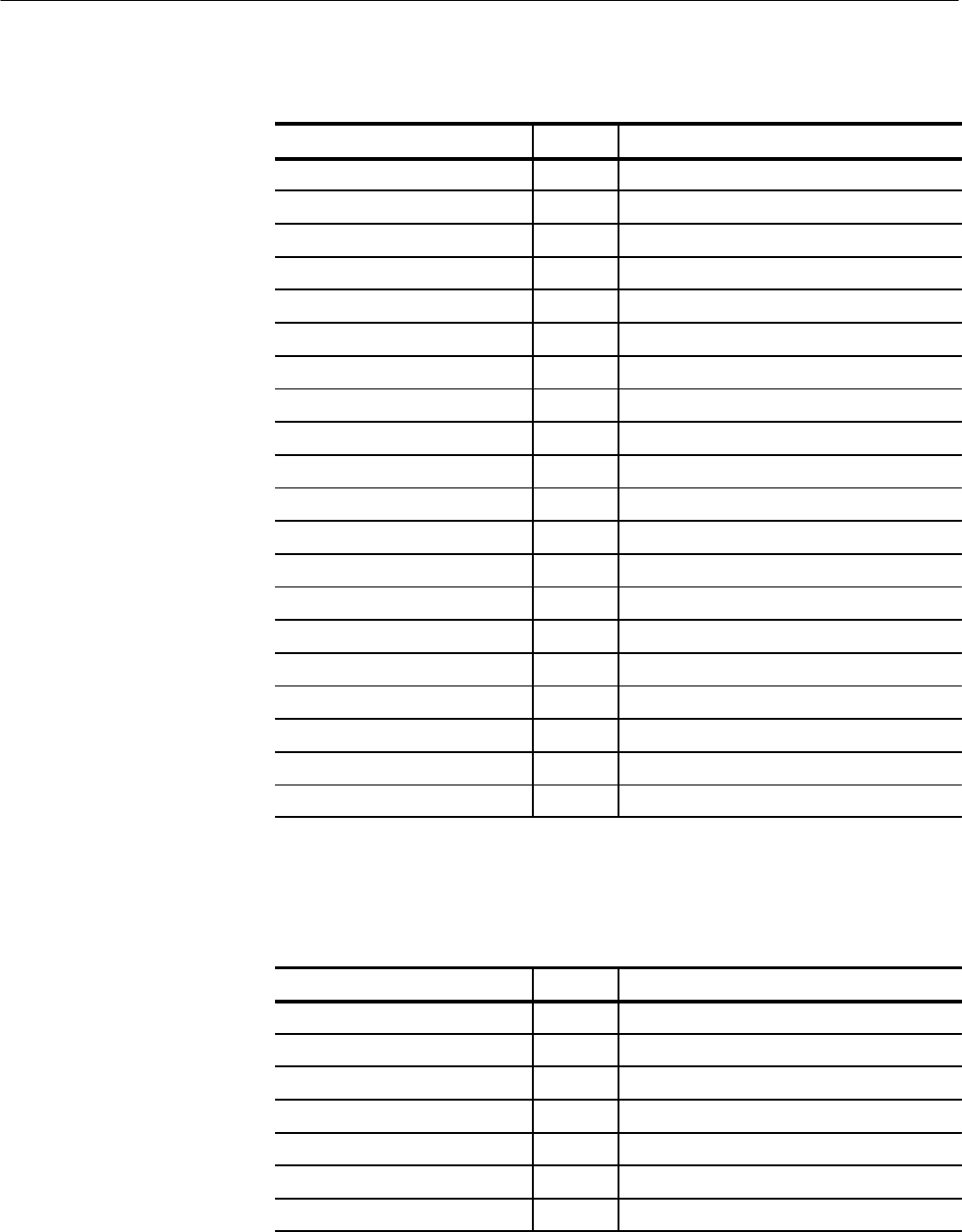
Table A-3 provides the CPU/DSP Interface Address Map.
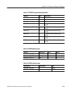
Table A-3: CPU/DSP interface address map
Address R/W Host function
6000 0020
1
R ICS Register Read
6000 0020 W ICS Register Write
6000 0024 R SEM Register Read
6000 0024 W SEM Register Write
6000 0028 R RX Register Read
6000 0028 W TX Register Write
6000 0030 R IVR Register Read
CPU/DSP Interface
Address Map