


Theory of Operation
3–14
AM700 Audio Measurement Set Service Manual
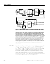
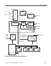
Digital Audio Board (A3)
The information for the A3 digital audio board is provided in two manners. First
is a discussion of the digital audio board functions as related to the user
interface. The first discussion follows the functional operation of the board. The
second part of the discussion more closely follows the schematic layout for the
digital audio board.
Digital audio signals from the front panel XLR connectors or the rear panel
connectors (BNC, optical, or, XLR) are processed for application to the DSP
(Digital Signal Processor) circuit board. The Digital Audio board is composed its
own DSP, the Digital Generator, and the Digital Receiver.
Digital Audio Board Terminology. The following terms are used in the discussion
of the functions of the digital audio board.
H Interface Signal. This is the voltage versus time waveform present on the
AES interface cable. The voltage changes represent a serial bit stream of 1’s
and 0’s. It is characterized by digital waveform parameters including:
amplitude, clock frequency, jitter, phase (relative to another interface signal),
and eye opening.
H Audio Data. This is the digital data conveyed by the interface signal. It can
be characterized by audio signal measurements such as level, distortion,
frequency, channel separation, and so on.
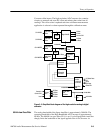
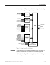
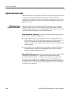
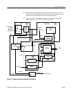
Main Audio Data Generation. Main Audio data generation includes both the AES
and the DSP generator modes. A simplified block diagram of the digital
generator is shown in Figure 3–5. Either of these generators may be used to
produce the same signals capable of being produced by the High Resolution
analog generator. In addition, the AES/EBU digital generator has a jittered sine
wave that is used to jitter modulate the digital signal to test for jitter immunity of
a circuit or device under test.
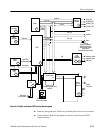
Digital Audio Board
Functional Description