


Removal and Replacement Procedures
6–60
AM700 Audio Measurement Set Service Manual
4. Remove one screw and the five standoffs securing the board. (Note: The
CRT display instruments have six screws and no standoffs holding the board
in place.)
5. Remove the screw from the metal standoff post holding the hybrid retaining
clip. Remove the metal standoff post using a 5/16-inch nutdriver and remove
the plastic screws and shoulder washer from the metal standoff post near
TP28. Do not remove the standoff post.
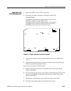
6. Lift the Analog Acquisition board away from the chassis.
Reverse the procedure to reinstall the Analog Acquisition board.
7. Position the Analog Acquisition board to align the screw holes in the board
with the threaded holes on the chassis.
8. Reinstall the T15 Torx retaining screws and the metal standoff post for the
hybrids.
9. Reinstall the hybrid retaining clip and screw.
10. Reinstall the plastic screw and shoulder washer. Do not substitute a metal
screw for the plastic one.
11. Reconnect the cables to the Analog Acquisition board disconnected in step 3.
12. Reconnect the cables to the Audio Generator board disconnected in step 2.
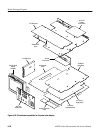
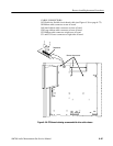
1. Place the AM700 top down.
2. Remove the Analog Acquisition board (A1) to provide clearance to remove
and replace the XLR board. (See the Analog Acquisition board removal/re-
placement procedure.)
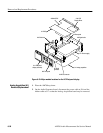
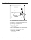
3. Disconnect the grey ribbon cable from the XLR board.
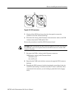
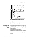
4. To release the XLR connectors from their housings on the front panel, insert
a filed down 3/32-inch flat-bit screwdriver into the small slot in the center of
each XLR connector. Press and turn counterclockwise (less than 1/4 turn
required). See Figure 6–25.
XLR Connector (A2)
Removal/Replacement