


Adjustment Procedures
5–12
AM700 Audio Measurement Set Service Manual
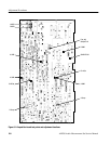
The following procedure requires removal of the instrument cabinet and some of
the circuit board assemblies to remove and replace the CRT display monitor
assembly. The procedure assumes that a part of the CRT display monitor
assembly is being replaced for a factory service repair. Refer to the Remove and
Replacement Procedures in the Maintenance section of this manual and the
exploded views given in the Replaceable Mechanical Parts section to assist you
if necessary.
When replacing the entire CRT display monitor assembly with a prealigned
exchange assembly, make only those adjustments needed to satisfy the require-
ment of the verification procedure referred to in the preceding paragraphs.
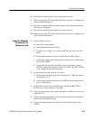
1. Remove the CPU, the DSP, the Digital audio board, and the power supply
shield
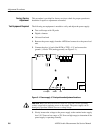
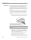
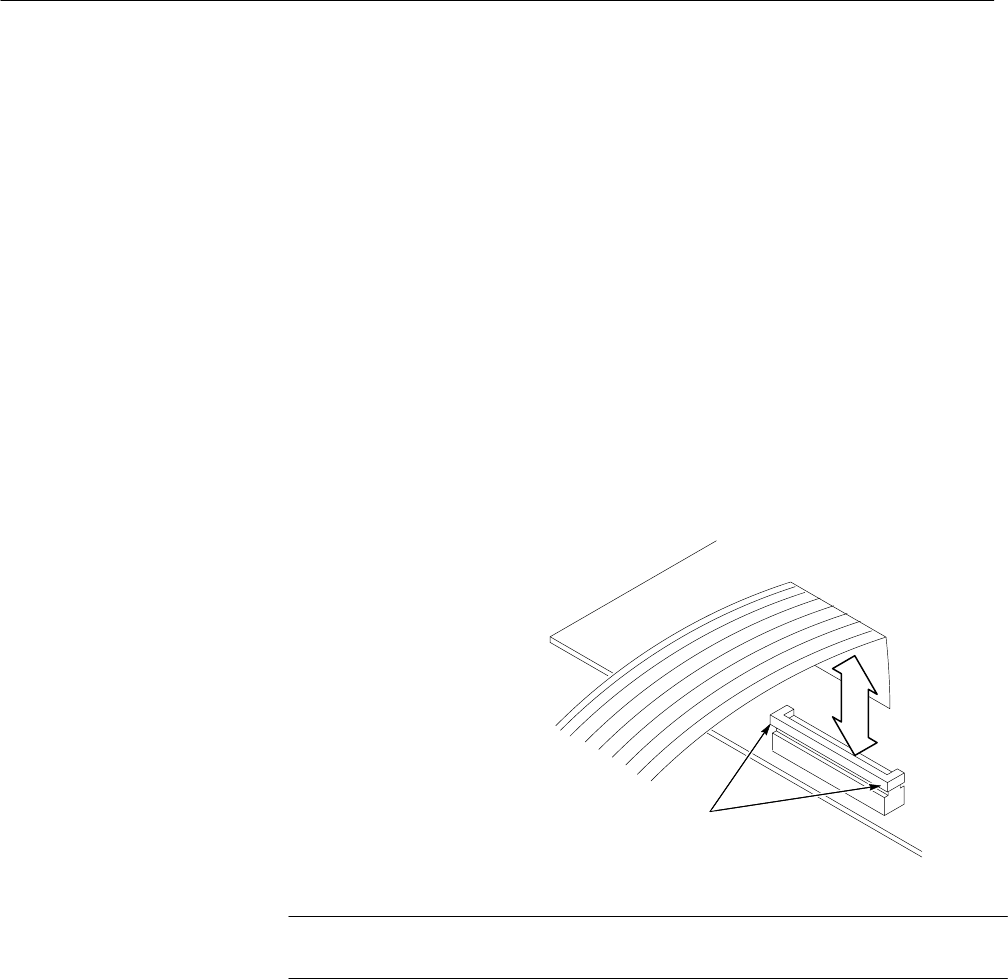
a. Disconnect the flexible floppy disk drive cable on from J42 on the CPU
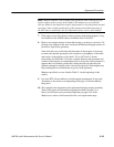
board by lifting the side latches on the housing first (see Figure 5–3).
Lift the connector release bar from its ends to loosen the cable.
Press the release bar down to lock the cable to the connector.
Figure 5–3: Disk drive flexible circuit board connector operation
NOTE. Do not pull on the cable to force it out of the connector. This will weaken
the connection.
b. Remove the three circuit board mounting screws around the fan and
flexible cable connector and the rear panel screws holding the CPU
board. Note: there is one screw in the rear panel that is different from
other screws; it has a built-in (captive) washer. Use the correct screw at
this location when reassembling the CPU board.
c. Disconnect all the cables attached to CPU, DSP, and Digital Audio
circuit boards that come from the other circuit boards.
d. Pull the CPU and DSP assembly forward gently about 1/4 inch. The
boards should come out as a single assembled unit. Set them aside on an
Preparation to Align