Table of Contents
xii
AM700 Audio Measurement Set Service Manual
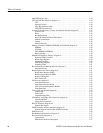
Figure 3–7: Digital audio receiver simplified block diagram 3–19. . . . . . . . . .
Figure 3–8: Digital audio connectors 3–29. . . . . . . . . . . . . . . . . . . . . . . . . . . .
Figure 3–9: Digital signal processor port connector 3–30. . . . . . . . . . . . . . . . .
Figure 3–10: DSP port timing diagram 3–31. . . . . . . . . . . . . . . . . . . . . . . . . . .
Figure 3–11: Analog generator simplified block diagram 3–33. . . . . . . . . . . . .
Figure 3–12: Analog generator DSP section block diagram 3–35. . . . . . . . . . .
Figure 3–13: S-Clock disable used for DSP mode control 3–37. . . . . . . . . . . .
Figure 3–14: SSI clock, frame, B clock, and serial data waveform for
High Res and High BW modes 3–38. . . . . . . . . . . . . . . . . . . . . . . . . . . . . .
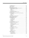
Figure 3–15: Switching waveform for –15 V floating power supply 3–44. . . .
Figure 3–16: Simplified block diagram of the A6 CPU board 3–45. . . . . . . . .
Figure 3–17: DSP board simplified block diagram 3–56. . . . . . . . . . . . . . . . . .
Figure 3–18: DSP/CPU host port interface 3–59. . . . . . . . . . . . . . . . . . . . . . . .
Figure 3–19: Picture monitor simplified block diagram 3–63. . . . . . . . . . . . . .
Figure 3–20: Power supply block diagram 3–67. . . . . . . . . . . . . . . . . . . . . . . .
Figure 3–21: LCD driver board block diagram 3–81. . . . . . . . . . . . . . . . . . . . .
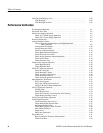
Figure 4–1: Interconnection cables 4–3. . . . . . . . . . . . . . . . . . . . . . . . . . . . . .
Figure 4–2: Input configuration control panel 4–6. . . . . . . . . . . . . . . . . . . . .
Figure 4–3: Audio generator controls 4–7. . . . . . . . . . . . . . . . . . . . . . . . . . . .
Figure 4–4: Generator control display 4–8. . . . . . . . . . . . . . . . . . . . . . . . . . . .
Figure 4–5: Waveform control display 4–9. . . . . . . . . . . . . . . . . . . . . . . . . . .
Figure 4–6: View window icons 4–9. . . . . . . . . . . . . . . . . . . . . . . . . . . . . . . .
Figure 4–7: Cable for generator output level check 4–11. . . . . . . . . . . . . . . . .
Figure 4–8: Advanced analog controls display 4–13. . . . . . . . . . . . . . . . . . . . .
Figure 4–9: Generator frequency check cable 4–13. . . . . . . . . . . . . . . . . . . . . .
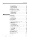
Figure 4–10: Keypad entry buttons 4–17. . . . . . . . . . . . . . . . . . . . . . . . . . . . . .
Figure 4–11: Impedance check adapter cables 4–19. . . . . . . . . . . . . . . . . . . . .
Figure 4–12: Applications buttons 4–20. . . . . . . . . . . . . . . . . . . . . . . . . . . . . .
Figure 4–13: Input Configuration control panel 4–21. . . . . . . . . . . . . . . . . . . .
Figure 4–14: Audio Analyzer graphical display with real time (RT)
view visible 4–22. . . . . . . . . . . . . . . . . . . . . . . . . . . . . . . . . . . . . . . . . . . . .
Figure 4–15: Keypad entry buttons 4–22. . . . . . . . . . . . . . . . . . . . . . . . . . . . . .
Figure 4–16: Audio Analyzer main menu with input range and input
select submenus 4–24. . . . . . . . . . . . . . . . . . . . . . . . . . . . . . . . . . . . . . . . .
Figure 4–17: FFT Analyzer Window menu display 4–29. . . . . . . . . . . . . . . . .
Figure 4–18: Dual BNC to 110 W XLR adapter cable 4–38. . . . . . . . . . . . . . .
Figure 4–19: Dual BNC to dual XLR cable adapter 4–47. . . . . . . . . . . . . . . . .
Figure 4–20: Dual BNC to 110 XLR female adapter cable 4–48. . . . . . . . . . .


