Appendix A: Memory and Register Mapping
A-6
AM700 Audio Measurement Set Service Manual
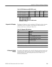
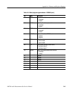
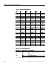
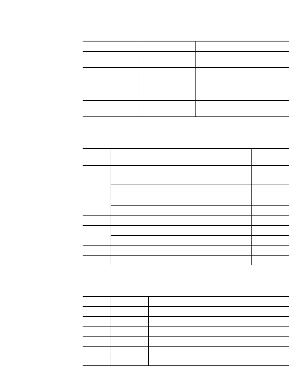
Table A-11: Dip switch S3 functional specification
DIP SWITCH S3 Switch position Descriptions
1 UP
DOWN
Normal System Operation
Disable 30 mS Timer
2 UP
DOWN
Normal System Operation
Cache disabled
3 UP
DOWN
Normal System Operation
Reset CPU only
4 UP
DOWN
Normal System Operation
Reset ALL hardware except CPU
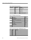
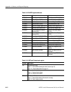
Table A-12: CPU MC68040 interrupts priority table
Interrupt
level
Interrupt source
BPR interrupt
mask bit
7 NVRAM Battery Failure B20
6
a. Serial Ports A & B B18
b. Serial Ports C & D Ports (KeyBoard Interface) B19
5
a. GPIB B16
b. Front Panel B17
4 DSP Board, Digital Audio Board, Generator Board B15, B24
3
a. Video Retrace B13
b. 68681 counter/timer B14
2 LANCE B12
1 Real Time Clock B11
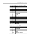
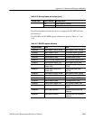
Table A-13: Board status register address: 12000000 Operation: read only
Bit Name Description
0 ERR0 0 = byte 0 parity error detected
1 ERR1 0 = byte 1 parity error detected
2 ERR2 0 = byte 2 parity error detected
3 ERR3 0 = byte 3 parity error detected
4 DPD0 DRAM Present bit 0
5 DPD1 DRAM Present bit 1


