Theory of Operation
AM700 Audio Measurement Set Service Manual
3–45
8
1
4
3
7
9
10
11
2
5
3
6
25
A8
To DSP DMA
and
Host Interface
IRQ
Memery
CPU and DSP
Bus Interface
Controller
NVRAM
Flash EPROM
EPROM
DRAM
and
Diagnostic
Display
Option
Board
Bus Arbitration
System Clock
RS232
GPIB
Video ASIC
VRAM DAC
I/O Processor
Board
Registers
and
Timer
and
Interrupt
Encoder
and Resets,
Counter and
Address
Decoder
Serial
Interface
and
VRAM
and
Floppy Drive
Interface
Board
Register
Bits
BusInterrupt
Request Arbitration
Control
Signals
Latch Control Signal
4–Wire Interface
To Front Panel Board
To Floppy Disk Drive
RGB & SYNC
RGB & SYNC
To LCD Driver
To VGA Monitor
To Internal Monitor (CRT)
To RS232
To Keyboard
Connectors
Connector
To GPIB
Port
Connector
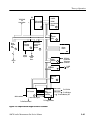
Figure 3–16: Simplified block diagram of the A6 CPU board


