Removal and Replacement Procedures
6–86
AM700 Audio Measurement Set Service Manual
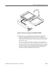
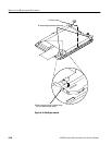
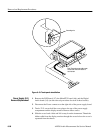
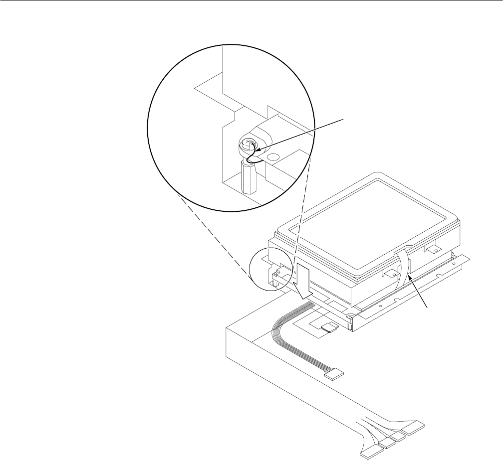
Grounding wire
Slot
Note: The touch screen cable comes
out the side of the new version of
touch screen.
Figure 6–43: Touch panel reinstallation
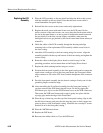
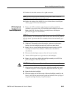
1. Remove the DSP board (A7), the Main/CPU board (A6), and the Digital
Audio board (A3) (see the removal procedures for each of those boards).
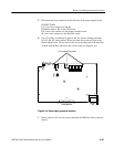
2. Disconnect the Power connectors at the right side of the power supply board.
3. Twelve T-15 screws hold the cover plate to the top of the power supply
compartment and the display monitor. Remove these screws.
4. Slide the cover back a little and lift it away from the instrument. Thread the
ribbon cable from the display monitor through the access hole as the cover is
separated from the chassis.
Power Supply (A11)
Removal/Replacement


