Adjustment Procedures
AM700 Audio Measurement Set Service Manual
5–21
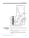
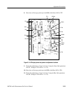
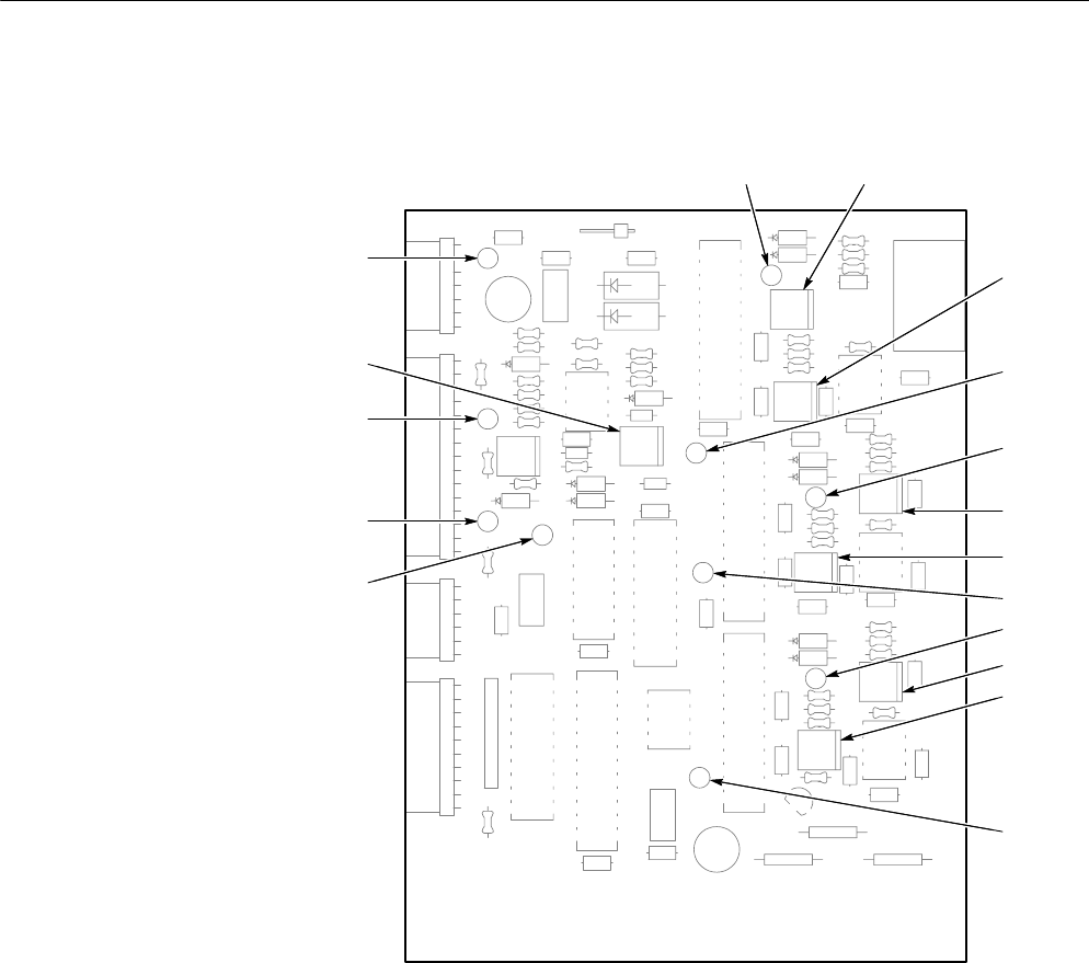
8. Move the oscilloscope probe tip to the MSB of the Green ADC at TP7.
C1
C31
C30
P4
C26
CR12
CR13
U11
J8
CR10
CR11
CR6
CR7
CR5
CR2
CR4
CR1
CR3
CR8
CR9
U10
U9
U8
U13
R47
U4
U12
U1
U5
U6
U7
C27
C29
C13
C15
C17
C16
C11
C4
C3
C33
C28
R24
R44
R16
R21
R26
R31
R17
R22
R27
R18
R23
R28
R40
R34
R15
R35
R19
R42
R25
R3
R12
R2
R9
R11
R10
R5
R4
R45
R29
R36
R30
R13
R1
R38
R32
R14
R33
R43
R20
R6
R7
R8
R41
R39
R37
TP6
TP7
TP8
TP4
TP10
TP5
TP2
TP3
C22
F1
F2
F3
L1
L3
L2
U3
C5
R51
TP9
C23
R49
P5
P1
P2
P3
R46
R50
R48
R52
C20C25
C8
C10
C14
C7
C24 C19
C9
C12
C6
C2
C18
C32
C21
TP1
R Gain
G Gain
B Gain
R Offset
G Offset
B Offset
TP1
TP2
TP3
TP4
TP5
TP6
TP7
TP8
TP9
TP10
BRT
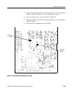
Figure 5–5: LCD display driver test points and adjustment locations
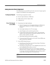
9. Repeat the adjustments of step 6 and step 7 using the Green Gain potentiom-
eter, R7. (Voltage at TP3 will be ≈ +1.4 V.)
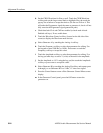
10. Move the oscilloscope probe tip to the MSB of the Blue ADC at TP8.
11. Repeat the adjustments of step 6 and step 7 using the Blue Gain potentiom-
eter, R9. (Voltage at TP4 will be ≈ +1.4 V.)


