


Theory of Operation
AM700 Audio Measurement Set Service Manual
3–43
The second output is the Overload signal that is applied to the attenuator setting
selector of the overloaded channel. This immediately adds a factor of 16
attenuation to protect the output amplifiers in that channel from damage.
The output impedance selection for the audio analog generator is done with
solid-state relays using control signal from the serial control register (diagram 2).
One-half of the total output impedance is in each side of the differential output.
The straight-through path of the impedance selectors produces an output
impedance of 10 W with 5 W in each side. The other choices are 600 W and
150 W. The resistance values that make up the 600 W and 150 W source
impedances are selected to account for the 10 W in each side that is not able to be
switched out of the output path. Either the 10 W or the 42 dB attenuator remains
in the generator output path to protect it from a short circuit on the output.
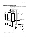
Power and Floating Power Supply (diagram 9)
Refer to schematic diagram 9 of the A5 analog generator circuit board for the
following circuit description.
The incoming power to the A5 audio generator board is applied through J16. The
fusing and decoupling circuitry for the various supplies to the board are shown in
this diagram.
In LCD color flat panel display instruments, these supplies are located on the
Power Supply board (A11), and the Generator board components for the floating
supply, if present, will not be in use.
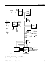
The floating power supply provides the isolated voltages to power the audio
generator. This isolation permits the generator outputs to float with respect to
chassis ground. A +22 V supply line provides power to the inputs of three
switching power supplies, U81 (+15 V), U82 (+5 V), and U83 (–15 V). On the
output of the switchers, the filter circuitry is referenced to the analog ground of
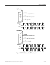
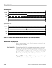
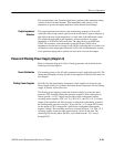
the floating audio generator circuitry. To provide the –15 V output, the circuitry
on the output of U83 is arranged in a buck-boost configuration that outputs
negative voltage. The switching waveform is shown in Figure 3–15. The –15 V
switching supply circuit provides approximately 150 mA to the load. The
remaining load current, about 200 mA, is provided from the –22 V source
through R359.
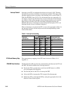
Output Impedance
Selectors
Power Distribution
Floating Power Supplies