Appendix A: Memory and Register Mapping
A-14
AM700 Audio Measurement Set Service Manual
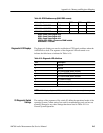
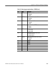
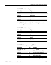
Table A-23: Port B memory map summary (DSP side)
Address (hex) Type Description
a. CC00 0000 – CC0F FFFF R/W DMA access DRAM 4MB
b. CC00 0000 – CC1F FFFF 8 MB
×
a. 1fff 0000 – 2000 FFFF R/W SRAM 128k
×
32
×
b. 1ffd 0000 – 2000 FFFF 256k × 32
$5000 0000 W DMA Process Reset Register (PRR)
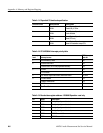
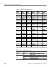
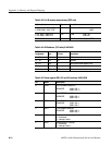
Table A-24: AHR address (CPU side): $1900 0000
AHR bit
assignment
Type
Default value
(in hex)
Description
31 .. 28 R 0 ASIC version number
27 .. 20 R/W 10 reserved
19 .. 16 R/W 5 DMA Process reset register (PRR)
15 .. 8 R/W 60 Host Port interface base address
7 .. 0 R/W CC DMA transfer base address
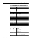
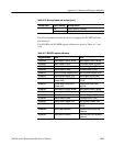
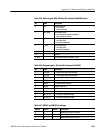
Table A-25: Status register (SR), U52 and U53, address: $4000 0000
Bit Name Description
0 APD0 Port A SCRAM Present Bit 0
SRAM SIZE (128K × 32) : 1
(256K × 32) : 0
1 APD1 Port A SRAM Present Bit 1
SRAM SIZE (128K × 32) : 1
(256K × 32) : 1
2 BPD0 Port B SRAM Present Bit 1
SRAM SIZE (128K × 32) : 1
(256K × 32) : 1
3 BPD1 Port B SRAM Present Bit 1
SRAM SIZE (128K × 32) : 1
(256K × 32) : 1
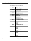
4 ACQ0 Sample receiver 0 interrupt
1 = no interrupt
0 = interrupt is active
5 ACQ1 Sample receiver 1 interrupt
1 = no interrupt
0 = interrupt is active


