


Theory of Operation
3–46
AM700 Audio Measurement Set Service Manual
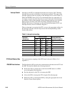
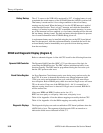
Interrupts to the CPU are multiplexed with the reset levels by U65. The three
interrupt lines provide an indication of an interrupt condition. The states of the
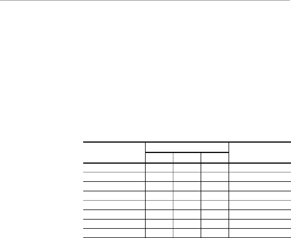
interrupt signals provide an encoding of the interrupt level as seen in Table 3–1.
While the RST040L line to U65 is low, the interrupt lines are connected to all
low inputs. At power up, after the power on reset is removed, all the interrupts
are enabled. As the system operates, various interrupt masks are set to prevent
higher priority activities of the CPU from being interrupted until they are
finished. The sources of interrupts are discussed in the description of U51, the
Interrupt Encoder, shown in schematic diagram 5.
When an interrupt is recognized, the CPU vectors to the appropriate address for
the interrupt level that occurred and processes the interrupt handling routine
found at that address.
Table 3–1: Interrupt level encoding
Control line status
Requested
interrupt level
IPL2
IPL1 IPL0
Interrupt mask level
required for recognition
0 High High High N/A
1 High High Low 0
2 High Low High 0-1
3 High Low Low 0-2
4 Low High High 0-3
5 Low High Low 0-4
6 Low Low High 0-5
7 Low Low Low 0-7
The system memory mapping of the CPU board is shown in Table A-2 of
Appendix A.
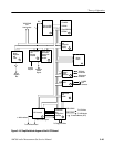
The Host Interface (HI) provides the communication path between the CPU and
the DSP. The interface handles the following functions:
H Permits the CPU to transfer data to and from the DSP (there is no DMA
access through the Host Interface).
H Provides the path for the CPU to bootstrap the DSP.
H Allows the DSP to interrupt the CPU using the Host Interrupt pin.
H Enables the CPU to interrupt the DSP by setting the appropriate bits in the
Interface Control Status register.
Interrupt Control
CPU Board Memory Map
CPU/DSP Host Interface