


Theory of Operation
3–18
AM700 Audio Measurement Set Service Manual
H Variable interface amplitude. Controls both the XLR and BNC output signal
amplitude in a 5:1 XLR to BNC ratio.
User Controlled Interface Parameters. The user can make the following parameter
changes to control the generated digital audio interface signal. Control of these
parameters depends on correct operation of specific hardware circuitry on the
Digital Audio board.
H Interface clock source selection. These selections are: Follow Audio,
Variable, or Ref In.
H Variable interface clock frequency. Available for use at sample frequencies
other than 48 kHz.
The second synthesizer circuit is similar to the first with a loop filter and
amplifier that drives a varactor in the second oscillator. This oscillator has an
output that is fed to a current-to-ttl converter to produces complementary
OFFSET and (OFFSET).
Reference Output Generation. The AES Reference output signal is present when
the AM700 is on. The reference clock frequency is the same as the main output
clock frequency. The variable main output parameters (jitter, amplitude, cable
simulator) do not affect Ref output. The audio data and channel status of the
Reference signal is fixed.
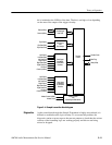
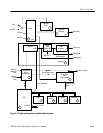
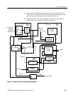
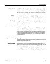
Digital Receiver. A simplified block diagram of the digital receiver is shown in
Figure 3–7. The following functional blocks receive the digital audio signal.
H Source selection. A solid-state FET switch selects the source of the digital
audio signal.
H AGC. The input signal is applied to the AGC circuit to provide about a 5 V
peak-to-peak signal at TP3 for any of the selected inputs.
H Auto-equalizer. Compensates for rolloff of the digital waveform from the
AGC output at TP3. The compensated waveform is on TP19. The Auto
Equalization circuitry provides a controllable amount of peaking to the
leading edge (or top) of the digital square-wave signal. Rolled off signals are
peaked to produce a flatter top signal while peaked signals are rolled off to
produce a flatter top signal.
With AGC and auto equalization, the AM700 is able to lock on to a wide
dynamic range of input signals that may be applied from external sources.
H AES decoder. The AES decoder decodes the serial data stream and outputs
data and clock signals to the Sample Transmitter.