


Theory of Operation
AM700 Audio Measurement Set Service Manual
3–47
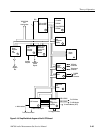
System Clock and Resets, Counter, and Address Decoder (diagram 2)
Refer to schematic diagram 2 of the A6 CPU board for the following discussion.
Three clock drivers, U47, U49, and U135, generate the various 25 MHz clocks
used throughout the CPU. These clock drivers are synchronized by the output of
Y2, a 12 MHz oscillator.
The power supply reset signal (PWRDY) is ANDed with the +5 V voltage, and
the RST line from U20 by AND-gate U59A. When any of those lines is low, the
CPU is reset. The output of U59A is applied to a clock driver, U47, to obtain
added time on the actual reset to the CPU to make sure a reset is completed
before the reset is released from the CPU. Assertion of the reset is the highest
priority interrupt to the CPU.
The power on reset is used to prevent the CPU from random activity while the
power is coming up to the correcting operating level. A manual reset caused by
pressing the reset button may be used to reinitialize the CPU to recover from a
failure. A manual reset is may be used in troubleshooting the AM700, and is not
a normal operating control. A reset aborts any processing in progress when it is
recognized. That processing is not recoverable.
When the reset is removed from the CPU, instructions are fetched from
predetermined vectors to begin the reinitialization of the CPU. After these initial
instructions are fetched, the program begins execution. If an access fault or
address error occurs during this reset processing sequence, a double bus fault is
generated, and the CPU halts operation.
If the host CPU (MC68040) indicates that a double bus fault condition has
occurred, LED (DS9) will light up. Hardware reset is required to restart the host
CPU.
There are five input sources that can assert the RESET pin of MC68040 and
DSP96002 and resetting its interface circuitry. They are the following:
H PowerUp Reset Controller
H Hardware Reset Dip Switch S6 SW3
H Host Processor Instruction Reset CMD
H Power Supply Ready Input
H Manual System Reset Button
System Clock
Reset
Bus Halt Indicator
Host CPU Reset
Functional Description