


Removal and Replacement Procedures
6–56
AM700 Audio Measurement Set Service Manual
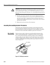
CAUTION. In step 4, when the instrument cover is replaced it can cause damage
to both cables and components. To avoid damaging parts, replace the cover
slowly and without force, making sure all cables and components are cleared as
the cover is lowered into place. Keep the cover evenly aligned with the chassis as
it goes on.
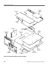
4. Start the cover evenly on all sides of the rear panel. Slide the instrument
cover onto the measurement set; as you do so, be careful that the cover does
not catch on any cables or components. Check on all sides as the cover is
sliding into place taking special precautions with the ribbon cables along the
right side of the AM700.
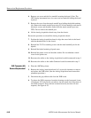
5. Replace the four feet on the rear of the instrument.
Assembly Removal/Replacement Procedures
The following removal/replacement procedures assume the power has been
disconnected and the instrument cover has been removed. (Refer to the Cover
Removal instructions on page 6–55.) Removal of some assemblies also requires
the removal of one or more other assemblies to gain access for removal.
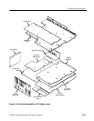
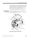
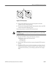
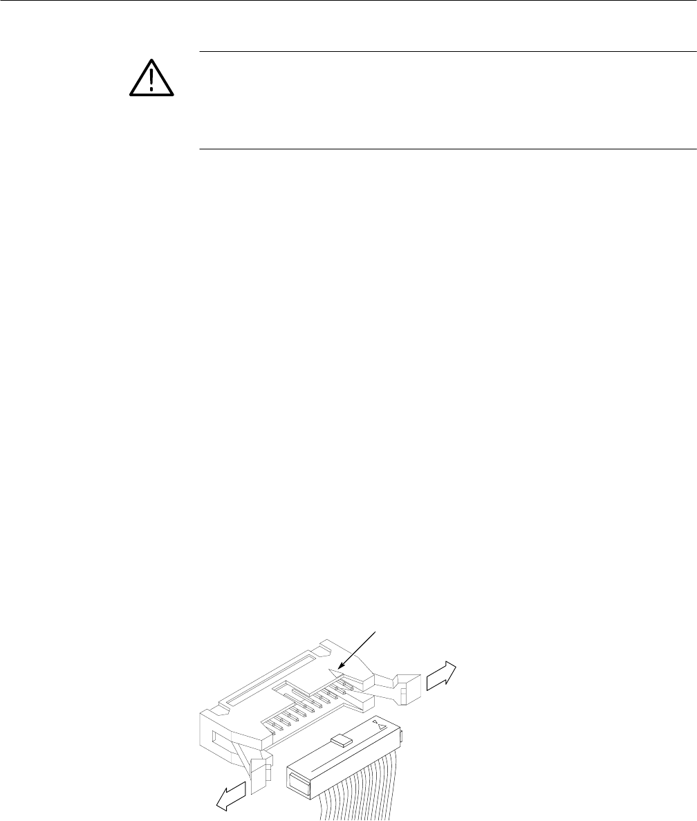
Signals and power supply voltages are passed through the instrument with a
system of interconnecting cables. A triangular key symbol is used to identify
pin 1 on the circuit board and the connector housing to assist in aligning the
connector with correct pins. Figure 6–21 shows the location of pin 1 (and the
triangular marking) on the connector housing of the clamping interconnections
used in the AM700. Release the holding catches by pressing each outward, as
shown in Figure 6–21.
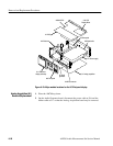
Pin 1 indicator
Figure 6–21: Multiple-pin connectors
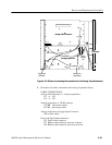
Major Assembly
Interconnection