


Diagnostics
AM700 Audio Measurement Set Service Manual
6–39
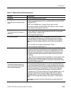
8. Move stack and frame pointers to the DRAM.
a. Encode the 8-bit boot step number into the USP LSByte.
b. Write “8” on the diagnostic LED display.
c. Set registers SP and a6 to the BOOT STACK PTR in DRAM
(0x3015fffc if DL’d code; else 0x301fffc).
9. If not skipping, test Boot ROM CRC.
a. Encode the 8-bit boot step number into the USP LSByte.
b. Write “9” on the diagnostic LED display.
c. Calculate a 32-bit CRC for all but the last long word of Boot ROM and
compare the value to the last word.
d. If CRC’s don’t match, flash 9 on the Diagnostic LED display several
times.
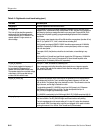
10. Copy data segment from ROM to DRAM.
a. Encode the 8-bit boot step number into the USP LSByte.
b. Write “A” on the diagnostic LED display.
c. Call the C startup routine to do the copy.
11. Upgrade the exception handler.
a. Encode the 8-bit boot step number into the USP LSByte.
b. Write “B” on the diagnostic LED display.
c. Write 11 to step code (in Boot RAM).
d. Copy the reset vectors from the ROM table to the RAM and one set of
the rest of the RAM vectors.
e. Change the VBR (Vector Base Register) to use the RAM vector table for
use with the “dumb” exception handler.
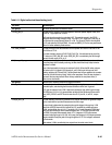
12. Initialize linkage to external libraries.
a. Write “C” on the diagnostic LED display.
b. Write 12 to step code (in Boot RAM).
c. Call the application-specific initialization routine.