


Diagnostics
AM700 Audio Measurement Set Service Manual
6–47
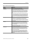
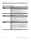
Table 6–11: Digital audio circuit board testing (cont.)
Test name Test description
Test group 3 Receiver tests, Generator tests which require the receiver.
3.7 eq_level_test This test internally connects the generator to the receiver and checks static operation of
the equalizer with the generator’s cable simulator off and then on.
The equalizer’s input is the agc’d input signal from TP3. If the input signal resembles a
square wave with a flat top, then the equalizer does nothing to it and it is reproduced at
TP19 with an amplitude of about 4 Vp-p. If the input signal, TP3, is rolled off in the way
the cable simulator does, then the equalizer applies peaking to keep the output (TP1)
square.
The amount of equalization applied is represented by the voltage EQ_LEVEL from U3A
pin 1, which is read by the slow adc U137. The only other input to the equalizer is GAIN
from TP1. If the input signal level is below minimum spec, then this level rises enough to
cause VR1 to conduct, which then disables the equalizer by pulling U132B pin 5 above
approximately 2 V. This is to prevent large noise at the equalizer output when there is no
input.
3.8 eq_response This test internally connects the generator to the receiver and checks dynamic operation
of the equalizer by continuously toggling the generator’s cable simulator off and on.
EQ_LEVEL, U3A pin 1, is monitored at J33 pin 8 for correct transient response.
See test 3.7 above for a description of static operation of the equalizer. The dynamic time
constants are set by any of the gain-setting resistors in the control loop, and by C211 and
C11 on U3A and U3B.
3.9 main_lock This test internally connects the generator to the receiver and checks the locking
operation of the main decoder U86. It checks for lock, then pulses MAIN_RELOCK to
force U86 out of lock. It then waits 0.5 sec to check that the receiver has re-locked. If it
hasn’t, it pulses MAIN_RELOCK again. The cycle repeats up to 3 times. The test fails
after the 3rd unsuccessful try.
U86 pin 9 should be an AES signal. Lock status is encoded in the state of U86 pins 4, 5,
and 6 which go to the DSP through the serial control chain. MAIN_RELOCK and
ER_CLEAR come from the serial control chain.
3.10 jitter_dc_test This test internally connects the generator to the receiver and checks operation of the
receiver phase counter U139 and U140. Phase of the main input is measured with
respect to the phase of the reference input. The generator phase is set to 0, +5 UI, and
–5 UI with respect to the reference generator. The test checks that the same value is
measured by the receiver phase counter.
Inputs to the counter in U139 and U140 are INMCK, INCBL, REFMCK, and REFCBL.
They come directly from the main and reference decoders. Each decoder must be
operating normally to generate these signals. They should AES signal inputs,* _RELOCK
signals should be low. *MCK is 12.288 MHz ttl clock signal, *_CBL is a pulse with a
40 msec period.