


Theory of Operation
3–78
AM700 Audio Measurement Set Service Manual
The variable-speed fan is powered from a thermally controlled +16 to +28 V
supply. A graph of the fan drive voltage versus the temperature is shown in
Figure . Temperature sensing is done by RT2, a thermistor mounted on the 5 V
heat sink. There are provisions for two additional temperature sensing elements
in the main instrument, one of which is connected to the Main CPU heat sink.
Thermistor RT2 has a negative temperature coefficient, so as the temperature
rises, the voltage at the junction of R97 and RT2 decreases. When the tempera-
ture gets high enough that the voltage biases on CR39, the input to U14A begins
to follow the temperature changes. The three temperature sense inputs are
diode-OR’ed at the non-inverting input of U14A, a voltage follower operational
amplifier. The highest sensed temperature controls the input to U14A by biasing
off the diodes that have a higher voltage on their cathodes.
The output of U14A is summed with the voltage feedback from the output of the
fan power supply. The feedback signal varies the output switching signal from
U15, a Pulse-Width Modulator. Without the temperature feedback through R101,
the feedback through R102 sets the output voltage to minimum, at about
+16.5 V. The added temperature feedback modifies that provided from the fan
drive circuit to vary the duty cycle of the drive signals to Q10 in proportion to
the temperature. The output of U14A decreases as the temperature increases, so
the feedback voltage at pin 2 of U15 decreases. This makes the Pulse-Width
Modulator output turn Q10 on for longer periods of time to increase the drive
voltage to the fan.
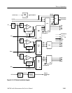
The Fan Drive circuit, composed of Q10, L10, CR42, and C75, is a boosted
power supply to produce the variable drive voltage to the fan. The pulse width
modulator and Q24 are powered from the +16.5 V supply, but the boosted
voltage to the fan can be up to 28 VDC. When Q10 conducts, energy is stored in
the magnetic field of L10. As Q10 shuts down, the energy must be returned to
the circuit. The voltage on the anode of CR42 increases due to the inductive rise
and the diode is biased on.
The energy is rapidly transferred to C75 and CR42 becomes reverse biased to
remove the inductor from the circuit. Until the next pulse of energy from L10,
the stored charge of C75 supplies the drive voltage to the fan. The Pulse-Width
Modulator and feedback circuit controls the fan drive voltage within a range of
+16 to +28 VDC. If Q10 remains off, the voltage on C75 will reduce to below
the +16.5 V supply and CR42 will again become forward biased through L10, so
the minimum output drive voltage to the fan is approximately +16 VDC.
Jumper J4 is a servicing jumper. When it is removed, the ground reference to the
feedback input is removed, and the PWM shuts off. The fan drive then reduces to
minimum. Jumper J4 is for testing purposes only. It may be pulled to eliminate
the feedback signals from the input of U15. Troubleshooting should be attempted
only by an experienced service person.
Fan Drive