


AM700 Audio Measurement Set Service Manual
9–1
Diagrams
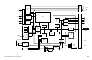
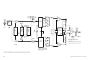
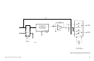
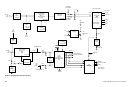
This section provides detailed block diagrams of the circuit boards and the
schematic circuit diagrams. Each module may have one or many schematic
diagrams to illustration the complete circuitry of the module. Schematic
diagrams are number by circuit board, beginning at diagram 1 for each module.
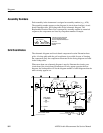
Block Diagrams
Each module in the instrument is assigned an assembly number (for example,
A20). The assembly number appears on the block diagram. The overall block
diagram is at the board level. The more detailed block diagrams of the modules
are more in depth than those in the Theory section with the discussion of the
module circuit operation.
Diagram Symbols
Graphic symbols and class designation letters are based on ANSI Standard
Y32.2–1975. Logic symbology is based on ANSI Y32.14–1973 in terms of
positive logic. Logic symbols depict the logic function performed and may differ
from the manufacturer’s data.
Overline, parenthesis, or leading slash indicate a low asserting state.
Example: ID CONTROL,
(ID CONTROL), or /ID CONTROL.
Abbreviations are based on ANSI Y1.1–1972. Other ANSI standards that are
used in the preparation of diagrams by Tektronix, Inc. are:
Y14.15, 1966 — Drafting Practices.
Y14.2, 1973 — Line Conventions and Lettering.
Y10.5, 1968 — Letter Symbols for Quantities Used in Electrical Science
and Electrical Engineering
American National Standard Institute
1430 Broadway, New York, New York 10018
Component Values
Electrical components shown on the diagrams are in the following units unless
noted otherwise:
Capacitors Values one or greater are in picofarads (pF).
Values less than one are in microfarads (mF).
Resistors Ohms (W).