Removal and Replacement Procedures
6–70
AM700 Audio Measurement Set Service Manual
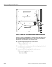
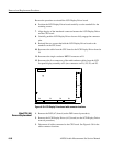
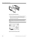
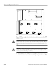
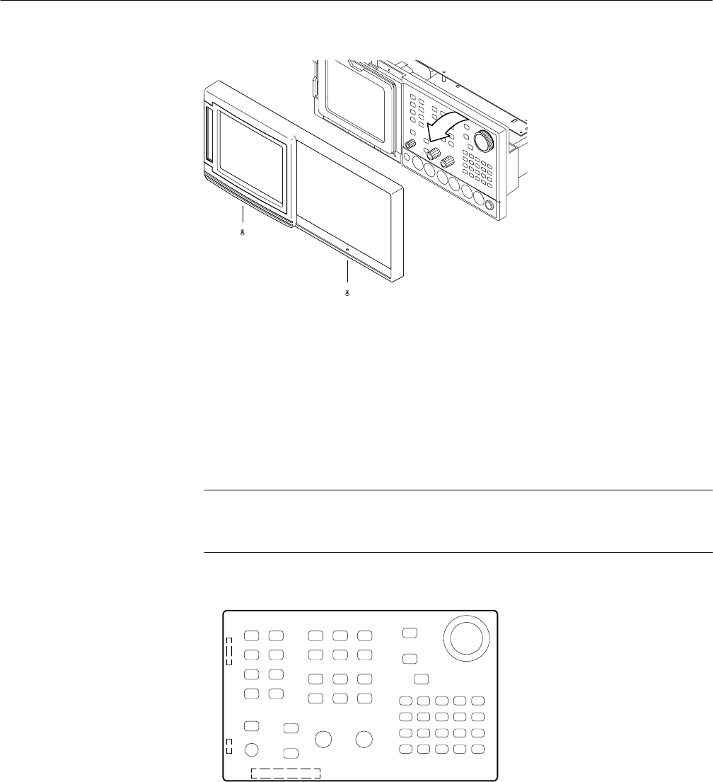
Figure 6–33: Trim ring and front panel removal
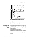
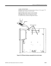
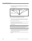
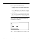
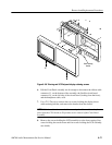
4. Pull the Front Panel assembly out far enough to disconnect the ribbon cable
connector, J1, on the bottom of the assembly; the flexible circuit board
connector (to the touch screen), J4, on the left side of the circuit board
(looking from the front); and the headphone cable, at J6. See Figure 6–34 for
connector locations on the circuit board.
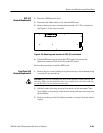
NOTE. If the cabinet is removed, disconnecting the ribbon cable to the front
panel from the CPU board at J50 permits easier removal of the Front Panel
assembly.
J4
J6
J1
Figure 6–34: Front panel board connector locations


