9–6
AM700 Audio Measurement Set Service Manual
Differential
Input
XLR
Input
Chassis
STAR
RF
Reject
K2 (K1)
K5 (K4)
CAL 1+
CAL 1–
K2 (K1)
K5 (K4)
K29 (K28)
K29 (K28)
150 Term
150 Term
U114
CAL
Input
200
OVLD
Circuitry
600
and
OVLD
Sense
gives
150
Total
WW
W
J29
Generator
Source
K26,K31
(K24,K30)
Generator
Source
R321
(R320)
K26,K31
(K24,K30)
CH A (CH B)
COMP
Input
Attenuator
100W
Input
Attenuator
100W
0
–12
–24
–36
–36
–24
–12
0
K20 (K10)
K21 (K11)
K22 (K12)
K23 (K13)
K20 (K10)
K21 (K11)
K22 (K12)
K23 (K13)
Clamps
to
10V
±
+
–
+
–
U3A (U1A)
U3B (U1B)
+
–
U4 (U2)
U17,U20
(U5,U8)
Gain Set
0,+8,+12 dB
K27B (K25B)
Gain
0 or 18 dB
K27C (K29C)
Gain
0 or 18 dB
TP8 (TP4)
2.00 Vrms
Full Scale
Attenuator: 0 to 36 dB (12 dB steps)
Include Gain = +6 dB for 6 dB Steps
(Vmax in = 125 Vrms)
ARANGE
CH A OUT
(CH B OUT)
Gain: 0 to 30 dB in 6 dB Steps
Max Sensitivity = 62.5 mVrms Full Scale
For K27 and K29
Nor mally Closed = Resistors in Parallel = Unity Gain
If activated, Normally Open Contacts = 18 dB Gain
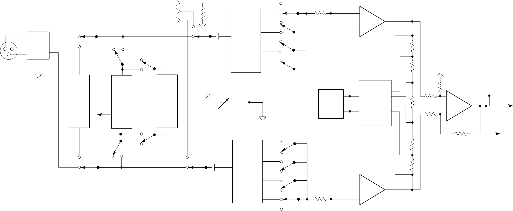
Figure 9–2: Analog Acquisition Channel A input section (Channel B in parentheses)


