


Theory of Operation
AM700 Audio Measurement Set Service Manual
3–55
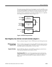
RS232C Interface (diagram 10)
Refer to schematic diagram 10 of the A6 CPU board for the following discus-
sion.
Two dual universal asynchronous receiver/transmitter (DUART) are used in this
design. UARTA (U29) is used for the RS232 serial ports. UARTB (U39) channel
A is setup for interfacing with the Audio Generator and channel B is used as
keyboard interface.
The DUARTs themselves consist of eight major sections: internal control logic,
timing logic, interrupt control logic, a bidirectional 8-bit data bus buffer, two
independent communication channels, a 6-bit parallel input port, and a 8-bit
parallel output port.
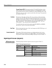
The operation of the DUARTs are programmed by writing control words into the
appropriate registers. Operational feedback is provided by the status registers
which are then read by the CPU.
Keyboard Interface. UART port B of U39 is configured as an interface for an AT
type keyboard. XT type keyboard protocols are not supported. The protocol for
serial data transmission is an 11-bit data stream composed of 1 start bit, 8 data
bits, 1 odd parity bit, and 1 stop bit. When troubleshooting the keyboard
interface, activity on the keyboard may be checked by observing the keyboard
serial line at TP5 with an oscilloscope to check the data stream.
Keyboard Interface Register Setup. The register setup for interfacing with the
keyboard is as follows:
H Clock-Select Register B
Both receiver-clock and transmitter-clock selects External Clock Inputs.
H Output Port Register (OPR)
Bits OP1, OP4, and OP6 are setup as general purpose outputs. A description
of the port signals is given in Table A-19.
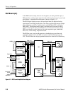
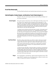
GPIB Controller and Host Interface (diagram 11)
Refer to schematic diagram 11 of the A6 CPU board for the following discus-
sion.
The GPIB interface provides a standard interface for communication between
instruments and remote control of the AM700. Table A-20 provides the address
information to the GPIB controller. Refer to the TMS9914A GPIB Controller
Data Book for detailed information on the controller device.
General Description
General Purpose Interface
Bus (GPIB) Controller