


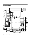

Theory of Operation
AM700 Audio Measurement Set Service Manual
3–7
At the output of the Attenuator a clamp circuit across the two sides of the
differential signal prevents the signal from exceeding + or –10 V. This clamp
protects the Input Amplifier from the accidental application of excessive signal
amplitudes that would damage it. If the autorange function is enabled, the
attenuator will be switched to the appropriate range for the applied signal.
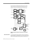
Gain Selection. Both sides of the differential input signal are handled on different
paths through the attenuator and gain stages. The positive phase of the signal is
applied to U3A, and the negative side is amplified through U3B. These gain
stages may be set for unity gain, 6 dB gain, or 12 dB gain. The separate outputs
are then applied to the Combining Amplifier, U4.
Amplifier U4 converts the differential audio signal into a single-ended signal.
This stage may be set for either unity gain or 18 dB gain. The overall gain is the
sum of the gain from the previous amplifiers and the input amplifier in dB. The
output of U4 may be viewed with an oscilloscope at TP6 for troubleshooting the
input circuitry. With an input signal applied, the output at TP6 should range
between 1 and 2 V
RMS
, with 2 V
RMS
being full scale to the A/D converter.
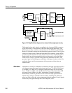
Tunable Notch Filters (diagram 3)
Refer to schematic diagram 3 of the A1A1 circuit board for the following circuit
description.
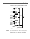
At the input to the Notch Filter, a solid-state relay, U35, either selects the notch
filter or permits the audio signal to bypass the filter completely. At the output of
the notch filter, another solid-state relay, U36 selects either the output of the
notch filter or the bypass signal to be applied to the A/D Converters. When in
use, the notch filter is tuned to the fundamental frequency so that it is notched by
20 dB. The notched signal is then amplified by 20 dB. This increases the
amplitude of the harmonic content in the signal so that harmonic distortion
measurements may more easily be made. The 20 dB gain is later removed from
the measurement readouts of harmonic distortion.
The center frequency of the notch is determined by the DSP. Binary data applied
to U29 determines the gain that is applied to the state variable notch, thus setting
its center frequency. At the notch frequency, the amount of signal passed is
reduced by greater than 20 dB. The current output steps from U29 are converted
to voltage by U33A, and the steps are reintegrated by U33B.
The reintegrated and out-of-phase signal is fed back to the input minus pin of
U31A where it is summed with the incoming analog signal. That output signal is
also summed with the input signal and the minus input of operational amplifier
U31B where it subtracts from the output of the operational amplifier at the notch
Differential-to-Single-
Ended Amplifier
Notch Selection
Multiplying DAC