


Theory of Operation
3–62
AM700 Audio Measurement Set Service Manual
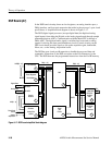
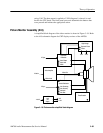
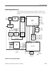
The resistive touch panel provides much of the interface between the user and the
applications. Front panel buttons are used to select applications and make
numerical entries, but the menus that control much of the operation are accessed
through the touch panel. The X and Y-axis coordinates of a touch on the panel
provide specific voltage level outputs from multiplexer U29. Those voltage are
digitized by A/D Converter U17. The 8-bit data word is applied to the parallel
input pins of registers U14 and U15 to form part of the 128-bit serial data
stream.
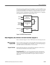
Headphone Amplifier and Speaker (diagram 2)
The Speaker is not enabled for the current version of firmware for the AM700.
Audio signal monitoring is available using the headphone jack of the front panel.
While monitoring the incoming audio signal, all measurements are suspended.
Left and right channel serial digital data is converted to left and right channel
analog signals by a dual 16-bit D/A converter, U19. The analog audio is
amplified by the Left and Right Channel amplifiers, U25A and U25B respec-
tively. A further amplifier stage on both channels provides the volume control
function for the stereo headphone output signal. Voltage followers on each
channel isolate the headphone amplifiers from the external headphones. The
voltage followers allow a wide range of headphone impedance to be tolerated.
Front-Panel LED Indicators (diagram 3)
There are four banks of LED indicators associated with the front panel. The
indicators are behind the front panel labels and are turned to indicate an active
front-panel button selection. Serial data to define the state of the LEDs is loaded
into a series four of 8-bit registers, U33 – U36. The output bits of registers U34 -
U36 are applied to line drivers U43 – U45 to drive the LEDs that are arranged in
pairs. Only two, single LEDs are connected to U33, so a line driver is not used
on its outputs. During power-on, the registers are reset. This reset turns on all the
front-panel LEDs so that is a good point to check that all the LEDs are func-
tional.
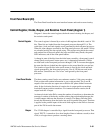
Front-Panel Push Buttons (diagram 4)
Each of the front-panel buttons is connected to one input of a bank of six,
parallel/serial in – serial output shift registers, U37 through U42. The parallel
inputs of the shift registers are normally high through pull-up resistors to +5 V.
When a button is pressed, the associated input is pulled low. Periodically, at a
rate fast enough to catch a button press, the data is latched (all the registers in the
128 bit shift register are latched at the same time). The entire serial data stream is
then clocked through the registers to the Data Out port on the last register in the
Touch Panel